background image

Revision 

04

February 19, 1998


363-765-104-04

30

PairGain

 Engineering - Plant Series


FRE-765

 List 

4x

Cabling Verification. 

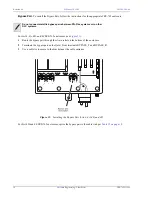
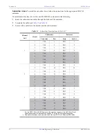
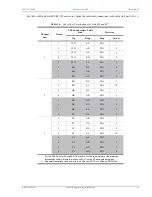
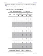
Verify the following connections:

1

Visually ensure that the ground wire is tightly secured to the grounding lug inside the FRE-765 and at the 
ground termination point.

2

Visually verify that the HDSL lines are terminated properly and with the correct orientation.  If the HDSL 
lines are not connected properly, the COT will not communicate with the FRE-765.

3

Verify that the HDSL lines are "dry."

a

Verify 0 Vdc between the Tip and Ring, Tip and ground, and Ring and ground of each of the HDSL pairs 
terminated at the FRE-765.

b

Verify a value greater than 100 k

 resistance between Tip and ground, and Ring and ground for each of 

the HDSL pairs terminated at the FRE-765.

Turn-Up and Testing

Refer to the COT Line Unit Technical Practice or RT Line Unit Technical Practice for complete COT and RT 
turn-up and testing procedures.

Troubleshooting

Refer to the COT Line Unit Technical Practice or RT Line Unit Technical Practice for complete COT and RT 
troubleshooting procedures.

TECHNICAL SUPPORT

PairGain Technical Assistance is available 24-hours-a-day, 7-days-a-week by contacting PairGain Customer 
Service Engineering group at: 

During normal business hours (8:00 AM to 5:00 PM, Pacific Time, Monday - Friday, excluding holidays), 
technical assistance calls are normally answered directly by a Customer Service Engineer.  At other times, a 
request for technical assistance is handled by an on-duty Customer Service Engineer through a callback process.  
This process normally results in a callback within 30 minutes of initiating the request.

In addition, PairGain maintains a computer bulletin board system for obtaining current information on PairGain 
products, product troubleshooting tips and aids, accessing helpful utilities, and for posting requests or questions.  
This system is available 24-hours-a-day by calling (714) 730-3299.  Transmission speeds up to 28.8 kbps are 
supported with a character format of 8-N-1.

Perform the following verifications before inserting any cards in the COT shelf.

Telephone:

(800) 638-0031 or (714) 832-9922 

Fax:

(714) 832-9924

Содержание 150-1365-04

Страница 1: ... 363 765 104 04 Revision History of This Practice Revision 04 February 19 1998 A Initial Release List Number Part Number CLEI Code 4 150 1365 04 VAMRBM0ARA 4A 150 1365 41 VAMRBN0ARA 4B 150 1365 42 VAMRBP0ARA 4D 150 1365 44 VAMRBR0ARA 4E 150 1365 45 VAMRBS0ARA 4F 150 1365 46 N A 4G 150 1365 47 VAMRBT0ARA 4H 150 1365 48 VAMRBU0ARA ...

Страница 2: ...f PairGain Technologies Inc Information contained in this document is company private to PairGain Technologies Inc and shall not be modified used copied reproduced or disclosed in whole or in part without the written consent of PairGain Other product names mentioned in this practice are used for identification purposes only and may be trademarks or registered trademarks of their respective compani...

Страница 3: ... 9 INSTALLATION AND TEST 13 Unpacking 13 Installation Requirements 14 Mounting 14 Wiring 16 Turn Up and Testing 30 Troubleshooting 30 TECHNICAL SUPPORT 30 WARRANTY AND CERTIFICATION 31 Warranty 31 Certification 31 ABBREVIATIONS 33 Using This Technical Practice Two types of messages identified by icons appear in the text These messages indicate special circumstances These messages indicate the poss...

Страница 4: ...Revision 04 February 19 1998 363 765 104 04 iv PairGain Engineering Plant Series FRE 765 List 4x ...

Страница 5: ...auxiliary power pairs when PG Flex is used with a PG Flex doubler The enclosure can be pole or wall mounted and is environmentally sealed for outside plant installations Listed below are the FRE 765 enclosures described in this practice List 4 see Figure 1 on page 2 List 4A see Figure 2 on page 2 List 4B see Figure 3 on page 3 List 4D and 4E see Figure 4 on page 3 List 4F see Figure 5 on page 4 Li...

Страница 6: ...Revision 04 February 19 1998 363 765 104 04 2 PairGain Engineering Plant Series FRE 765 List 4x Figure 1 FRE 765 List 4 RT Enclosure Interior View Figure 2 FRE 765 List 4A RT Enclosure Interior View ...

Страница 7: ...3 765 104 04 February 19 1998 Revision 04 FRE 765 List 4x PairGain Engineering Plant Series 3 Figure 3 FRE 765 List 4B RT Enclosure Interior View Figure 4 FRE 765 List 4D and 4E RT Enclosure Interior View ...

Страница 8: ...Revision 04 February 19 1998 363 765 104 04 4 PairGain Engineering Plant Series FRE 765 List 4x Figure 5 FRE 765 List 4F RT Enclosure Interior View Figure 6 FRE 765 List 4G RT Enclosure Interior View ...

Страница 9: ...l Office Terminal COT terminations with internal protectors for HDSL inputs and metallic bypass pair except 4G which is unprotected terminations can be added when PG Flex is used with a doubler included with 4G and 4H 3 4 1 11 2 2 inch cable entrance conduit knockouts with rubber grommet provided hinged cover for electronics inside RT Enclosure See Table 1 on page 6 to identify which features are ...

Страница 10: ...5 pair Amphenol male X AMP Insulation Displacement X 15 foot PVC Cable Stub X Subscriber 25 foot Air Core Cable Stub X Terminations 25 foot Gel Filled Cable Stub X 1 foot PVC Cable with Male Amphenol X 12 foot PVC Cable with Male Amphenol X RayChem MSP X Subscriber Protection 5 pin sockets short housing X X X X RayChem MSP X AMP Insulation Displacement X X X X HDSL RayChem MXC X Terminations RayCh...

Страница 11: ...levation 200 feet to 13 000 feet 60 m to 4 000 m Dimensions Weight List 4 21 2 lb 09 6 kg List 4A 26 3 lb 11 9 kg List 4B 22 7 lb 10 3 kg List 4D 30 4 lb 13 8 kg List 4E 30 4 lb 13 8 kg List 4F 25 0 lb 11 3 kg List 4G 25 5 lb 12 5 kg List 4H 29 2 lb 13 3 kg Lists 4 4A 4B 4D 4E 4F Height 19 25 in 48 9 cm Width 14 25 in 36 2 cm Depth 05 93 in 15 0 cm List 4H Height 21 25 in 53 9 cm Width 16 75 in 42...

Страница 12: ...h Ckt 4 are used for Tip and Ring terminations for channel units providing eight 8 circuits Ckt 1 through Ckt 8 are used for Tip and Ring terminations for a 24 channel system you can provision a maximum of 24 circuits Each PG Flex channel unit provides four 4 or eight 8 circuits Table 3 shows how the channels are assigned dependent on the type of service provided such as Plain Old Telephone Servic...

Страница 13: ... 3 Rcv T R 7 Ckt 7 Ckt 4 Tx T R 8 Ckt 8 Ckt 4 Rcv Table 4 FRE 765 List 4x Backplane Connectors List Connector or Fuse Go to On 4 4B 4G P1 Connector 12 24 channel systems Table 5 page 10 4A Subscriber terminations 12 24 channel systems Table 13 page 22 4D 4E Subscriber terminations 12 24 channel systems Table 16 page 25 4F Subscriber terminations 12 24 channel systems Table 17 page 26 4H Subscriber...

Страница 14: ...Connector for Lists 4 4B and 4G Channel Unit Circuit Backplane Connector P1 Lists 4 4B and 4G Subscriber Cable Stub List 4B only Tip Ring Tip Ring 1 26 1 WH BL BL WH 2 27 2 WH OR OR WH 3 28 3 WH GN GN WH 1 4 29 4 WH BN BN WH 5 30 5 WH SL SL WH 6 31 6 RD BL BL RD 7 32 7 RD OR OR RD 8 33 8 RD GN GN RD 1 34 9 RD BN BN RD 2 35 10 RD SL SL RD 3 36 11 BK BL BL BK 2 4 37 12 BK OR OR BK 5 38 13 BK GN GN B...

Страница 15: ... DDS Units Table 6 Connector P3 16 32 Channel Systems Channel Unit Circuit Backplane Connector P3 Subscriber Cable Stub Tip Ring Tip Ring 1 26 1 WH BL BL WH 2 27 2 WH OR OR WH 3 28 3 WH GN GN WH 1 4 29 4 WH BN BN WH 5 30 5 WH SL SL WH 6 31 6 RD BL BL RD 7 32 7 RD OR OR RD 8 33 8 RD GN GN RD 1 34 9 RD BN BN RD 2 35 10 RD SL SL RD 3 36 11 BK BL BL BK 2 4 37 12 BK OR OR BK 5 38 13 BK GN GN BK 6 39 14...

Страница 16: ...l Systems Channel Unit Circuit Backplane Connector P2 Subscriber Cable Stub Tip Ring Tip Ring 1 26 1 WH BL BL WH 2 27 2 WH OR OR WH 3 28 3 WH GN GN WH 3 4 29 4 WH BN BN WH 5 30 5 WH SL SL WH 6 31 6 RD BL BL RD 7 32 7 RD OR OR RD 8 33 8 RD GN GN RD 1 34 9 RD BN BN RD 2 35 10 RD SL SL RD 3 36 11 BK BL BL BK 4 4 37 12 BK OR OR BK 5 38 13 BK GN GN BK 6 39 14 BK BN BN BK 7 40 15 BK SL SL BK 8 41 16 YL ...

Страница 17: ...T enclosure is shipped with the CHASSIS GND wire wrap post connected to the adjacent GND wire wrap post on the RT Backplane Table 8 Test and Configuration Line Unit Terminations Connector Type Function ID_0 GND 045 in Wire wrap No connection reserved for future use ID_1 GND 045 in Wire wrap No connection reserved for future use ID_2 GND 045 in Wire wrap No connection reserved for future use TEST_I...

Страница 18: ...vides three 25 pair Amphenol connectors male for terminating the subscriber lines List 4A Provides AMP Quiet Front insulation displacement connections for subscriber terminations List 4B Provides one 15 foot PVC 25 pair cable stub List 4D Provides two 25 foot Air Core Cables for HDSL and Subscriber Terminations List 4E Provides two 25 foot Gel Filled Cables for HDSL and Subscriber Terminations Lis...

Страница 19: ...le is open 3 Install the grommet from the outside of the FRE 765 Hint Hold it at an angle to the hole and roll it into position 4 Ensure that the lip of the grommet rests on the bottom of the FRE 765 around the knockout hole 5 Use an appropriate tool to open the required hole s in the bottom of the grommet Figure 8 Installing the Grommet Recommend using one hole for both the HDSL and the bypass pa...

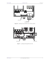
Страница 20: ...ure 11 1 Route the chassis ground wire through the small hole in the strain relief on the bottom of the enclosure 2 For Lists 4 4B and 4G connect one end of the chassis ground wire to the grounding lug see Figure 9 For Lists 4A 4D 4E 4F Figure 10 on page 17 and 4H Figure 11 on page 17 connect one end of the chassis ground wire to the grounding bar 3 Connect the other end of the chassis ground wire...

Страница 21: ...363 765 104 04 February 19 1998 Revision 04 FRE 765 List 4x PairGain Engineering Plant Series 17 Figure 10 Installing the Ground Wire List 4A 4D 4E and 4F Figure 11 Installing the Ground Wire List 4H ...

Страница 22: ...pe Function HDSL_1_T HDSL_1_R WH BL AMP Quiet Front or RayChem terminals Tip and Ring terminations for HDSL Pair 1 from the COT 130 Vdc is simplexed on this line for powering the RT HDSL_2_T HDSL_2_R WH OR AMP Quiet Front or RayChem terminals Tip and Ring terminations for HDSL Pair 2 from the COT 130 Vdc is simplexed on this line for powering the RT BYPASS_T BYPASS_R WH GN AMP Quiet Front or RayCh...

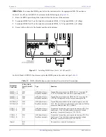
Страница 23: ... Route the HDSL pairs through the strain relief on the bottom of the enclosure 2 Terminate HDSL Pair 1 on the RayChem terminals HDSL_1_T Tip and HDSL_1_R Ring 3 Terminate HDSL Pair 2 on the RayChem terminals HDSL_2_T Tip and HDSL_2_R Ring 4 Secure with a cable tie to the bracket near the cable entrance Figure 13 Installing HDSL Lines Lists 4G Figure 14 Installing HDSL Lines List 4H ...

Страница 24: ... the bypass pair through the strain relief on the bottom of the enclosure 2 Terminate the bypass pair on the Quiet Front terminals BYPASS_T and BYPASS_R 3 Use a cable tie to secure to the bracket near the cable entrance Figure 15 Installing the Bypass Pair List 4 4A 4B and 4F For List 4D and 4E FRE 765 enclosures splice the bypass pair to the cable stub per Table 12 on page 18 Do not connect metal...

Страница 25: ...he List 4H FRE 765 enclosure refer to Figure 17 1 Route the bypass pair through the strain relief on the bottom of the enclosure 2 Terminate the bypass pair on the RayChem terminals BYPASS_T and BYPASS_R 3 Use a cable tie to secure to the bracket near the cable entrance Figure 16 Installing the Bypass Pair Lists 4G Figure 17 Installing the Bypass Pair List 4H ...

Страница 26: ...765 List 4A RT Enclosure the cable on the rear of the AMP Quiet Front termination module is installed in connector P1 on the RT enclosure backplane Shaded terminations used only with the 8 Channel POTS or 4 Channel DDS Units Table 13 Subscriber Terminations for List 4A Channel Unit Circuit Subscriber Protector Connector Pair Strip Socket 1 TB1 1 PB1 1 2 TB1 2 PB1 2 3 TB1 3 PB1 3 1 4 TB1 4 PB1 4 5 ...

Страница 27: ...1 on the RT enclosure backplane Shaded terminations used only with the 8 Channel POTS or 4 Channel DDS Units Table 14 Subscriber Terminations with internal proctectors for List 4H Channel Unit Circuit Subscriber Termination Protector Pair 1 1 1 2 2 2 3 3 3 1 4 4 4 5 5 5 6 6 6 7 7 7 8 8 8 1 9 9 2 10 10 3 11 11 2 4 12 12 5 13 13 6 14 14 7 15 15 8 16 16 1 17 17 2 18 18 3 19 19 3 4 20 20 5 21 21 6 22 ...

Страница 28: ...ation cable to backplane connector P1 For List 4G the Amphenol ended cable is connected to P1 For List 4B terminate subscriber lines to the cable stub that attaches to backplane connector P1 cable Table 15 Subscriber Terminations for Lists 4 4B and 4G Channel Unit Circuit Backplane Connector P1 Lists 4 4B and 4G Subscriber Cable Stub List 4B only Tip Ring Tip Ring 1 26 1 WH BL BL WH 2 27 2 WH OR O...

Страница 29: ...ckplane Shaded terminations used only with the 8 Channel POTS or 4 Channel DDS Units Table 16 Subscriber Terminations for Lists 4D and 4E Channel Unit Circuit 25 Pair Subscriber Cable Stub Protector Tip Ring Strip Socket 1 WH BL PB1 1 2 WH OR PB1 2 3 WH GN PB1 3 1 4 WH BN PB1 4 5 WH SL PB1 5 6 RD BL PB1 6 7 RD OR PB1 7 8 RD GN PB1 8 1 RD BN PB1 9 2 RD SL PB1 10 3 BK BL PB2 1 2 4 BK OR PB2 2 5 BK G...

Страница 30: ...the cable on the rear of the protection block subassembly is installed in connector P1 on the RT enclosure backplane Shaded terminations used only with the 8 Channel POTS or 4 Channel DDS Units Table 17 Subscriber Terminations for Lists 4F 12 24 channel systems Channel Unit Circuit 25 Pair Amphenol male Line Cable Protector Tip Ring Strip Socket 1 26 1 PB1 1 2 27 2 PB1 2 3 28 3 PB1 3 1 4 29 4 PB1 ...

Страница 31: ...ctor strips for each subscriber line installed see Figure 18 Figure 18 Installing Five Pin Protector Plugs See the following tables for protector socket assignments Table 13 Subscriber Terminations for List 4A on page 22 Table 16 Subscriber Terminations for Lists 4D and 4E on page 25 Table 17 Subscriber Terminations for Lists 4F 12 24 channel systems on page 26 Installer must provide suitable prim...

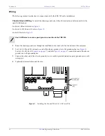
Страница 32: ...nnect a white jumper wire to PWR_2_T J12A and a blue jumper wire to PWR_2_R J13A wire wrap pins c Loosen the Phillips head screw for each connector and slide the bracket on the AMP Quiet Front termination under it d Tighten the Phillips head screw e Insert and tighten the white and blue jumper wires into the AMP Quiet Front terminations Figure 19 Installing Power Pair Terminations 2 For List 4 4A ...

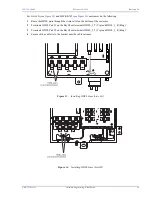
Страница 33: ... the auxiliary power pairs from the CO shelf to RayChem terminations through the strain relief on the bottom of the enclosure Use a cable tie to secure to the bracket near the cable entrance 2 Terminate the power pairs on the RayChem terminations per Figure 21 Figure 20 Installing Power Pairs List 4G Figure 21 Installing Power Pairs List 4H The RayChem terminations are factory installed in the FRE...

Страница 34: ...Line Unit Technical Practice or RT Line Unit Technical Practice for complete COT and RT troubleshooting procedures TECHNICAL SUPPORT PairGain Technical Assistance is available 24 hours a day 7 days a week by contacting PairGain Customer Service Engineering group at During normal business hours 8 00 AM to 5 00 PM Pacific Time Monday Friday excluding holidays technical assistance calls are normally ...

Страница 35: ...cations of the unit by anyone other than an authorized PairGain representative voids the warranty If a unit needs repair 1 Call PairGain for a Return Material Authorization RMA number at 800 370 9670 or fax your request to 714 730 2961 2 Return the defective unit freight prepaid along with a brief description of the problem to PairGain Repair Center 14352 Franklin Avenue Tustin California 92780 70...

Страница 36: ...encouraged to try to correct the interference by one or more of the following measures Reorient or relocate the receiving antenna Increase the separation between the equipment and receiver Connect the equipment into an outlet on a circuit different from that to which the receiver is connected Consult the dealer or an experienced radio TV technician for help The user is cautioned that changes and m...

Страница 37: ...ral Office COT Central Office Terminal CU Channel Unit DDS Digital Data System FCC Federal Communications Commission FRE PG Flex Remote Enclosure GND Ground HDSL High bit rate Digital Subscriber Line ISDN Integrated Services Digital Network MSP Modular Station Protector PIC Primary Interexchange Carrier POTS Plain Old Telephone Service RT Remote Terminal ...

Страница 38: ...Corporate Office 14402 Franklin Avenue Tustin CA 92780 Tel 714 832 9922 Fax 714 832 9924 For Technical Assistance 800 638 0031 ...

Отзывы: