


Accelnet Plus Micro Modules User Guide
16-01687 Rev 03
Copley Controls
Page 113 of 139
7
O
PERATIONAL
T
HEORY
D
RIVE
I
NPUT
P
OWER
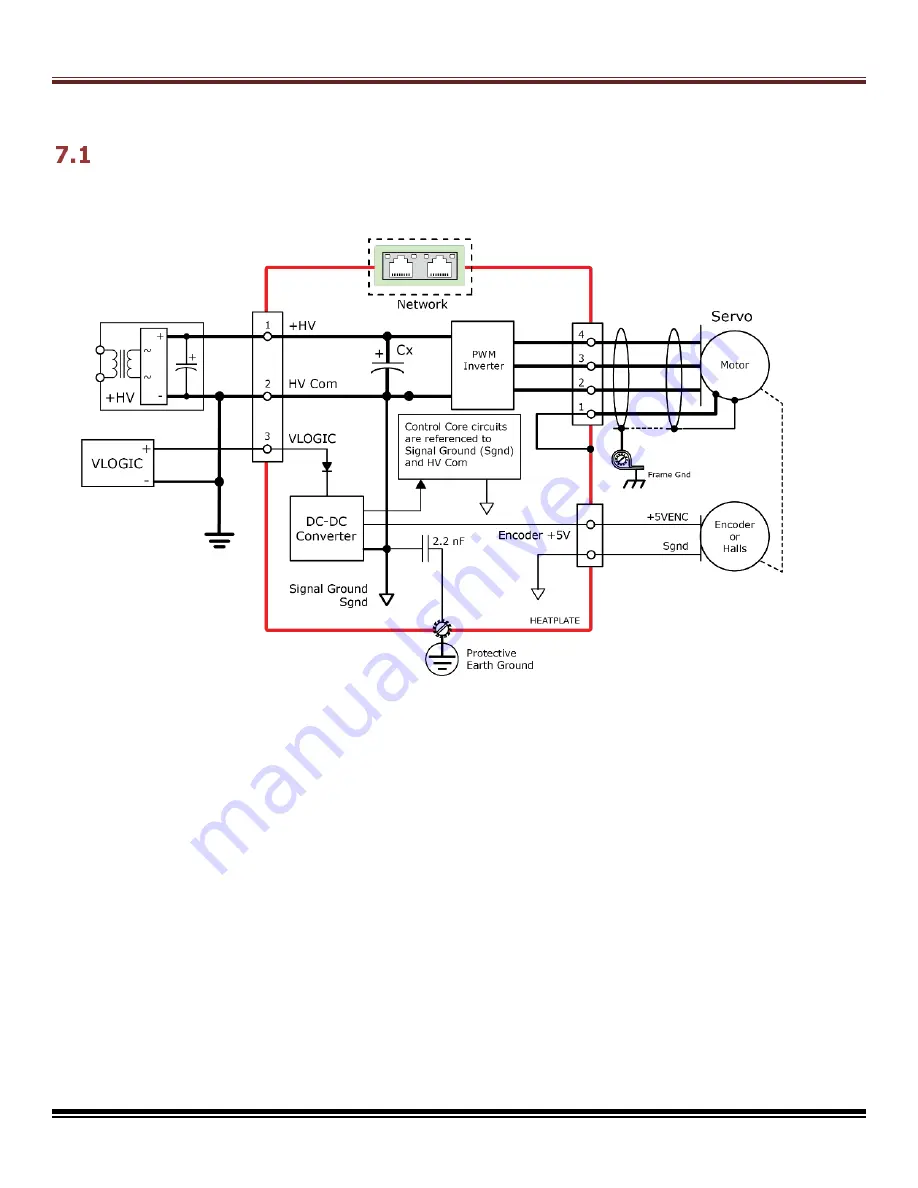
Power distribution within
Accelnet Plus Micro Modules
has a common ground which is isolated
from the heatplate. The CANopen & EtherCAT network signals are isolated from all of the drive
circuits.
VLOGIC
P
OWER
An internal DC/DC converter operates from the VLOGIC input and creates the logic/signal
operating voltages. This enables the drive to stay on-line when the +HV power has been
disconnected for emergency-stop or operator-intervention conditions. Network and serial
communications remain active so that the drive can be monitored by the control system when
the +HV is removed. The control core, feedback devices, and network connections are all
maintained by the VLOGIC power so that the system controller has visibility of the drive
status, motor position, I/O states, etc. When the +HV is 60 Vdc or less it, and the VLOGIC
can be driven from a single power supply. When using the STO feature, the VLOGIC must be
produced by a power supply with transformer isolation from the mains, PELV or SELV rating,
and a maximum output voltage of 60 Vdc.
+HV
P
OWER
The +HV input drives the high-voltage PWM outputs. When this is not connected to the
VLOGIC input, the full range of rated voltages can be used.


