Cool-Air Doors
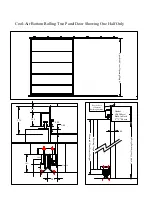
CSA-5-BR Bottom Rolling Slide Door
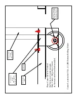
Assembly and Installation Instructions
1.
Open all structural component and hardware boxes
and compare with
itemized list in this instruction. Note: Structural components and hardware may
arrive in separate shipments.
2.
Install Top Guide
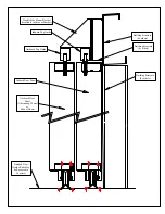
track per print. Use mounting brackets spaced per print. The
16 gauge box track top guide must be drilled for a 3/8” bolt at each mount
bracket. Depending on the print for the job this will be either 24” or 48” on center.
3.
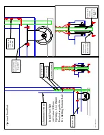
Install
1-1/4” X 1-1/4” X 1/8” structural steel angle (supplied by others)
bottom
guide
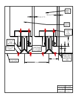
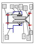
per print. Use supplied mount clips with two TapCon screws per clip four
foot on center and at each joint. Recommended to tack weld bracket to bottom
guide in slotted hole. One TapCon per bracket authorized if tack welded except at
joints. Recommend cutting exposed end of bottom guide at 45 Degree angle to
reduce sharp cutting edge.
4.
Measure
distance between
bottom of top track
and
top of bottom guide
.
5.
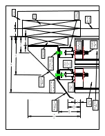
Allowing ¾” between top of door and bottom of top track and 3-1/2” for bottom
rail / bottom roller / bottom guide track,
trim vertical
to the measurement in step
4 minus 4-1/4”. Adjust if more or less space is needed between door and top track
or if different sized bottom guide is used.
6.
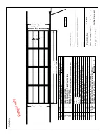
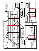
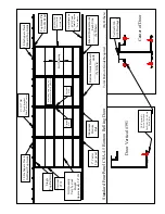
Lay out Door
structural components per component layout. Suggested to start
face down with protection to not scratch the paint.
7.
Install Top Rail Girt and Aluminum Bottom
Rail with one screw at each joint.
Check door print to determine quantity of top rail girts and determine if a bottom
rail reinforcing girt is supplied.
8.
Locate and place remaining girts
per the girt spacing. Numbers are starting
from top down. This may vary from the number specified if the verticals are
trimmed at site.
9.
Internal reinforcements
for the verticals are optional and may be supplied for
one or more vertical. If this vertical reinforcement girt section is supplied, install
the top girt for each panel, then install the reinforcing girt into the vertical, Tek
through the vertical near the top and near the bottom of the reinforcing member
and then butt the next horizontal girt tightly against the vertical reinforcing girt.
Continue this sequence all the way down. In some applications, a vertical
reinforcing girt will be supplied for only one side of the panel and not the other.
10.
Square the door panel
by measuring from corner to corner diagonally and
equalizing.
11.
Lay out optional
Walk Door Framed
opening (if supplied) per print. Install tek
screws in girt installed as door jamb inside vertical only on rear side (away from
“J” trim)
12.
Fasten
two tek screws at each joint on the rear of door


