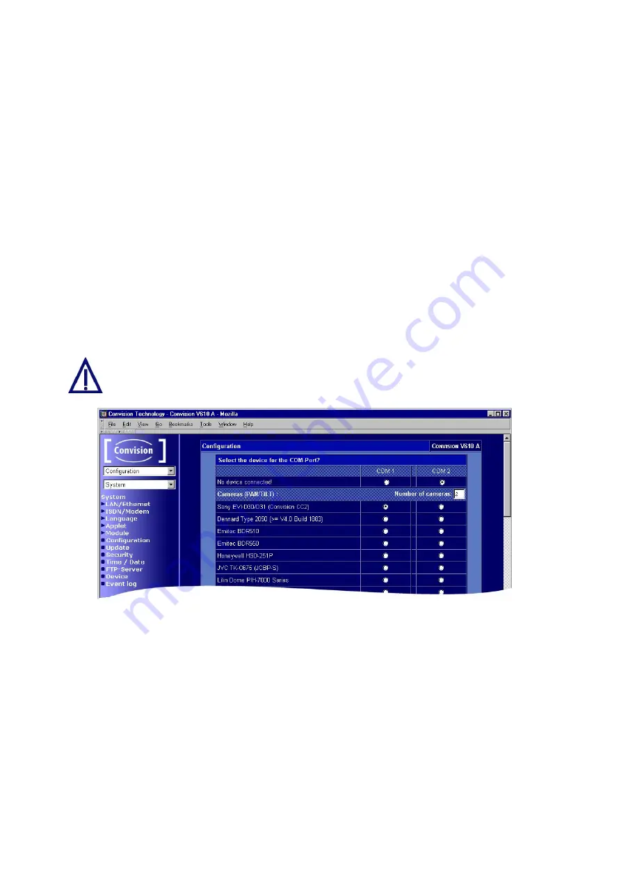
9.1.11 Assignment of Devices to the Serial Ports
In the "Device" menu you have to enter the devices connected to the two serial
interfaces (COM 1 and COM 2) of your Convision V6xx A.
1. In the table displayed, select which device is connected to COM 1 and COM 2. If
no devices are connected, select "No device connected!" (default).
2. If several controllable cameras are connected, specify the number of cameras.
3. As a rule, a modem is connected to COM2. For all the other devices (controllable
cameras, weather station, controllable sockets) you are free to choose the port.
4. If you want to operate a device not listed in the table, select "Serial Url Port". You
will control the device with your own applet that you have to upload to the
Convision V6xx A (refer to Chapter 8.6 and 9.1.4).
5. Save the data.
6. You will be prompted to reboot the device. For this purpose, click the "Reboot"
button.
You cannot connect two models of one device type (e.g. cameras) to the two
COM ports.
Figure 30: Assignments of the serial ports
Serial URL Port
Once the serial URL port has been activated, it is possible to control devices not
supported by the Convision V6xx A, e.g. other controllable cameras. In this case, all
the parameters required for setting the serial connection and the actual data will be
transferred.
The data that need to be entered for controlling the device can be obtained from the
device manufacturer.
When programming a website or an applet, you can integrate links or buttons that
include CGI parameters in addition to the IP address of the Convision V6xx A in the
- 52 -
Convision V600 A Series


