9
_______ Phillips Head Screw Driver, 3/16” Allen wrench (for input/output terminal blocks).
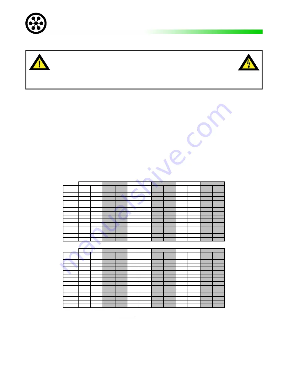
_______ For field wiring size, based on amperage and breaker sizes in table below. Units are rated for operation
up to 40 deg. C. Amb. Refer only to the matrix below for the service panel AC breaker size. The unit
comes standard with terminals for hard wire installation.
_______ Uninterruptible power systems require a ground wire. The grounded supply conductor (Neutral) wire should
be the same size as the input feed wires. The ground wire should be installed in accordance to NEC code.
The ground that feeds the UPS should be of good integrity and dedicated to the UPS. The run should be
as short as possible. Conduit cannot be used for the grounding of the circuit.
Reference:
NEC
ARTICLE
250
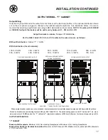
Based on breaker size and derating factor of 0.88 per NEC Table 310.16. The wire bending space on the “S” cabinet is 2” (i.e. maximum conductor of
3 AWG) and on the “T” cabinet is 7” (maximum conductor of 500 kcmil allowed – the terminal supports up to 2/0).
NOTE: Input currents alone are
maximum at full load, and when batteries are in recharge mode.
AC INPUT BREAKER AND CURRENT MATRIX
This unit is intended for installation in a temperature controlled, indoor area free of conductive contaminants.
TOOLS REQUIRED AND INSTALLATION CHECKLIST
120V
53A
60A
62A
70A
----
----
----
----
----
----
----
----
208V
30A
35A
36A
40A
41A
50A
46A
60A
51A
60A
54A
70A
208/120V
26A
35A
31A
40A
36A
50A
40A
60A
44A
60A
47A
70A
220V (50Hz)
29A
35A
34A
40A
39A
45A
43A
60A
48A
60A
51A
60A
230V (50Hz)
28A
35A
32A
40A
37A
45A
42A
50A
46A
60A
49A
70A
240V
26A
30A
31A
35A
36A
45A
40A
50A
44A
60A
47A
60A
240/120V
26A
30A
31A
35A
36A
45A
40A
50A
44A
60A
47A
60A
347V
18A
20A
21A
25A
25A
30A
28A
35A
30A
35A
33A
40A
380V (50Hz)
17A
20A
20A
25A
22A
30A
25A
30A
28A
40A
30A
35A
400V (50Hz)
16A
20A
19A
25A
21A
25A
24A
30A
26A
35A
28A
35A
415V (50Hz)
15A
20A
18A
20A
21A
25A
23A
30A
25A
35A
27A
35A
480V
13A
15A
15A
20A
18A
20A
20A
25A
22A
30A
23A
30A
600V
11A
15A
12A
15A
14A
20A
16A
20A
18A
20A
19A
25A
120V
----
----
----
----
----
----
----
----
----
----
----
----
208V
59A
70A
65A
80A
70A
90A
78A
100A
83A
125A
89A
125A
208/120V
52A
70A
56A
80A
61A
90A
68A
100A
72A
125A
77A
125A
220V (50Hz)
56A
70A
61A
80A
66A
90A
74A
100A
79A
100A
84A
125A
230V (50Hz)
54A
70A
59A
80A
63A
80A
71A
90A
75A
100A
80A
100A
240V
52A
70A
56A
70A
61A
80A
68A
90A
72A
90A
77A
100A
240/120V
52A
70A
56A
70A
61A
80A
68A
90A
72A
90A
77A
100A
347V
36A
50A
39A
50A
42A
60A
47A
60A
50A
70A
53A
70A
380V (50Hz)
33A
40A
35A
50A
38A
50A
43A
60A
46A
60A
48A
70A
400V (50Hz)
31A
40A
34A
40A
36A
50A
41A
60A
43A
60A
46A
60A
415V (50Hz)
30A
35A
32A
40A
35A
50A
39A
50A
42A
60A
44A
60A
480V
26A
30A
28A
35A
30A
40A
34A
45A
36A
45A
38A
50A
600V
21A
25A
22A
30A
24A
30A
27A
35A
29A
40A
31A
40A
INPUT MATRIX (KVA)
7.5KVA
11.0 KVA
10.0 KVA
13.5KVA
12.0 KVA
9.0 KVA
15.5 KVA
INPUT
CURRENT
INPUT
BREAKER
INPUT
VOLTAGE
INPUT
VOLTAGE
14.5 KVA
8.3 KVA
4.5 KVA
5.5 KVA
6.5 KVA
INPUT MATRIX (KVA)
INPUT
CURRENT
INPUT
BREAKER
INPUT
CURRENT
INPUT
BREAKER
INPUT
CURRENT
INPUT
BREAKER
INPUT
CURRENT
INPUT
BREAKER
INPUT
CURRENT
INPUT
BREAKER
INPUT
CURRENT
INPUT
BREAKER
INPUT
CURRENT
INPUT
BREAKER
INPUT
CURRENT
INPUT
BREAKER
INPUT
CURRENT
INPUT
BREAKER
INPUT
CURRENT
INPUT
BREAKER
INPUT
CURRENT
INPUT
BREAKER
PRELIMINARY INSTALLATION
***** CAUTION *****
To reduce risk of fire, connect only to maximum input current rated,
branch circuit overcurrent protection (see input breaker from table below)
in accordance with National Electrical Code, ANSI/NFPA 70.”
NOTE: 240/120V or 208/120V input MUST have 2 hots, neutral and ground for proper op-
eration and to prevent possible damage.
Содержание MODEL ES
Страница 51: ...51 APPENDIX A RELATIVE DRAWINGS SCHEMATICS APPENDIX A ...
Страница 57: ...57 NOTES ...


