


Safety
Information
Product
Information
Mechanical
Installation
Electrical
Installation
Getting
Started
Menu 0
Running
the motor
Optimisation
Macros
Advanced
Parameters
Technical
Data
Diagnostics
UL Listing
Information
Unidrive User Guide
95
Issue Number: 9 www.controltechniques.com
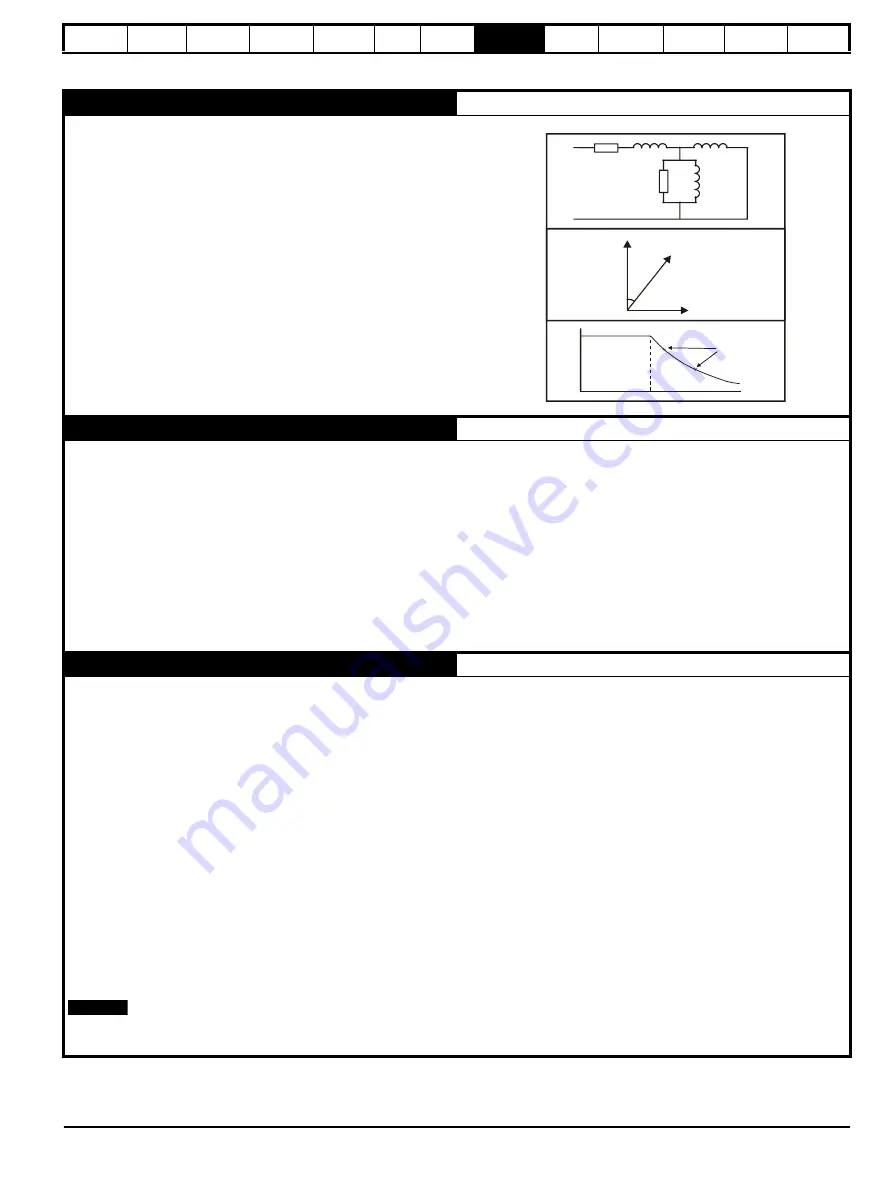
Pr 0.40 {5.12} Autotune
The motor must be stationary and disconnected from any load (including
the gearbox) before commencing an autotune.
The test is completed in three stages as follows:
1. Motor leakage inductance (Pr
5.24
)
Before the motor rotates the leakage inductance is measured. This is
required for the slip optimiser to work correctly.
2. Power factor (Pr
0.43
/
5.10
)
The motor runs up to two thirds base speed and the no load current
is measured. This equals the magnetising current which in
conjunction with the motor rated current value allows the power
factor to be calculated.
3. Saturation characteristic (Pr
5.29
/
5.30
)
The drive continues to turn the motor and while doing so gradually
reduces the magnetising current to determine the relationship
between magnetising current and motor flux for the specific motor
being controlled.
The saturation characteristic sets the levels at which the magnetising
current is controlled during operation above base speed (field
weakening).
Pr 5.27 Slip optimisation
Slip optimisation is used as follows:
1. To optimise the motor rated speed parameter from the motor nameplate value to the best value for the individual motor on a one off basis during
commissioning.
2. To constantly monitor and optimise the motor rated speed during normal operation to compensate for changes in motor temperature which can
have a significant effect on rotor resistance and thus rated speed.
The following conditions must apply for the slip optimiser to function correctly:
•
As detailed above in the autotune section the motor leakage inductance (Pr
5.24
) is required for this feature to function correctly. An autotune
should be carried out before enabling the slip optimiser.
•
The drive must run at a speed greater than
1
/
8
x rated speed.
•
At least
1
/
8
x rated load must be applied.
•
Slip optimisation can only be used at or below base speed. If field weakening operation is required the optimiser should be enabled during
commissioning only then disabled for high speed operation.
Pr 4.13 / 4.14 Current loop gains
The current loop gains control the response of the current loop to a change in current (torque) demand.
Inappropriate values entered in these parameters can cause the control system to become unstable.
The default values give satisfactory performance for most applications however for optimal performance in dynamic applications the values may
require tuning for the specific motor.
The current loop gains can be calculated from the motor resistance and inductance values by either:
1. Using the formula detailed below
2. The gain calculator wizard in Unisoft version 3.43 in the ’Tools’ menu
The proportional gain (Pr
4.13
) should be set to 1800 x Pr
5.24
x 10
-3
x Pr
11.32
where:
Pr
5.24
= per phase motor leakage inductance (mH)
Pr
11.32
= Drive rated current
The integral gain (Pr
4.14
) should be set to 0.044 x Pr
4.13
x
where:
Pr
4.13
= current loop proportional gain calculated above
R
= per phase stator resistance (from the motor data sheet)
Pr
5.24
= per phase motor leakage inductance (mH)
The numerical value in Pr
5.24
should be input directly into the above formula in mH
The x 10
-3
term converts this to H.
cos =
?
∅
L = ?
S
T
Nm
N rpm
= ?
R
Pr5.24 10
3
–
×
---------------------------------
NOTE
Содержание Unidrive 1 Series
Страница 208: ......


