


Safety
Information
Product
Information
Mechanical
Installation
Electrical
Installation
Getting
Started
Menu 0
Running
the motor
Optimisation
Macros
Advanced
Parameters
Technical
Data
Diagnostics
UL Listing
Information
Unidrive User Guide
93
Issue Number: 9 www.controltechniques.com
Pr 0.07 {5.14} Voltage mode
The voltage mode selects whether the drive is in open loop vector mode or fixed boost.
Fixed boost (
Fd
) should be used for fans and pumps and multiple motor applications.
Open loop vector is the default setting and should be used to tune the drive to the motor characteristic to get good performance at low output
frequencies.
Open loop vector mode requires the stator resistance and voltage offset parameters for ideal operation.
These can be measured by the drive depending on the voltage mode selected as follows:
Ur_I
= Stator resistance and voltage offset are measured on power up providing no trip condition is present and the drive enable (terminal 30) signal
is active.
Ur_S
= Stator resistance and voltage offset are measured every time the run command is activated. This mode ensures the drive compensates for
any change in the motor parameters due to temperature changes.
Ur
= No test is performed - a test should be carried out using one of the other modes or the stator resistance entered manually. (The voltage offset
cannot be entered manually as this is also a function of the drive.) This mode should be used where it is not desirable for the drive to test the motor
on power up or before a run.
The stator resistance and voltage offset values can be viewed in Pr
5.17
and Pr
5.23
respectively.
Pr 0.40 {5.12} Autotune
The motor must be disconnected from any load including the gearbox before commencing an autotune.
Once the test is enabled the drive runs the motor to two thirds base speed and measures the no load current which equals the magnetising current.
From the no load current and the motor rated current the drive then calculates the power factor.
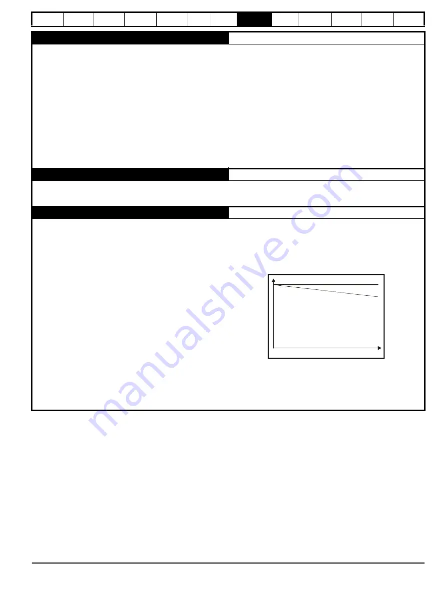
Pr 5.27 Slip compensation and Pr 0.45 {5.08} Motor rated speed
When a motor being controlled in open loop mode has load applied a
characteristic of the motor is that the output speed droops in proportion
to the load applied as shown aside:
In order to prevent the speed droop shown above slip compensation
should be enabled.
Pr
5.27
must be set to a 1 (this is the default setting) and the motor rated
speed must be entered in Pr
0.45
{
5.08
}. to enable slip compensation.
The motor rated speed parameter should be set to the synchronous
speed of the motor minus the slip speed. This is often displayed on the
motor nameplate.
i.e. For a typical 18.5 kW, 50 Hz, 4 pole motor the motor rated speed is
1465 rpm
The synchronous speed for a 4 pole motor is 1500 rpm therefore the slip
speed is 35 rpm
If the synchronous speed is entered slip compensation will have no
effect.
If too small a value is entered the motor will run faster than the
demanded frequency.
Synchronous speeds for different numbers of poles are as follows:
2 pole = 3,000 rpm
4 pole = 1,500 rpm
6 pole = 1,000 rpm
8 pole = 750 rpm
Shaft speed
Demanded speed
Load
Содержание Unidrive 1 Series
Страница 208: ......


