


Safety
Information
Product
Information
Mechanical
Installation
Electrical
Installation
Getting
Started
Menu 0
Running
the motor
Optimisation
Macros
Advanced
Parameters
Technical
Data
Diagnostics
UL Listing
Information
182
Unidrive User Guide
www.controltechniques.com Issue Number: 9
10.22 Advanced Features
This section gives information on some of the commonly
used advanced functions of the Unidrive.
10.22.1 Braking modes
0
Stnd.Hd
Standard ramp with ramp hold
1 FASt Fast
ramp
2
Stnd.Ct
Standard ramp with P control
The acceleration ramp is not affected by the ramp mode, and the ramp
output will rise at the programmed acceleration rate (subject to the
current limits programmed in the drive).
Stnd.Hd (0): Standard ramp with ramp hold
The deceleration ramp will be frozen if the DC Bus voltage rises above
the standard ramp voltage (Pr
2.08
). Normally the DC Bus voltage will
then begin to fall as the machine should stop regenerating. Once the
voltage drops below the standard ramp voltage, the ramp will again
begin to fall. This type of control does not usually give smooth
deceleration especially if the machine is lightly loaded, however it is
easy to set up.
FASt (1): Fast ramp
The output of the ramp will fall at the programmed deceleration rate
(subject to the current limits programmed in the drive). This mode should
be used when a braking resistor is fitted.
Stnd.Ct (2): Standard ramp with P control
The voltage rising to the standard ramp level (Pr
2.08
) causes a
proportional controller to operate, the output of which changes the
demanded current in the motor. As the controller regulates the DC Bus
voltage, the motor deceleration increases as the speed approaches zero
speed. When the motor deceleration rate reaches the programmed
deceleration rate the controller ceases to operate and the drive
continues to decelerate at the programmed rate. This gives smoother
control than standard hold mode. If the standard ramp voltage (Pr
2.08
)
is set lower than the nominal DC Bus level the drive will not decelerate
but will coast to rest. The standard controlled mode is most likely to be
useful in applications where smooth deceleration is required, particularly
with lightly loaded machines, or where the supply voltage is high where
the drive would trip on OV (DC Bus over voltage) due to the transients
produced in standard hold mode.
The output of the ramp controller (when active) is a current demand that
is fed to the frequency changing current controller (open loop) or the
torque producing current controller (closed loop). The gain of these
controllers can be modified with Pr
4.13
and Pr
4.14
.
This voltage is used as the level for both standard ramp modes. If hold
mode is used and this is set too low the drive will never stop, and if it is
too high and no braking resistor is used the drive may trip on OV (DC
Bus over voltage). If standard ramp with P control is used and this
parameter is set too low the machine will coast to rest, and if it is set too
high and no braking resistor is used it may trip on OV. The minimum
level should be greater than the voltage produced on the DC Bus by the
highest supply voltage.
Normally the DC Bus voltage will be approximately the rms supply
voltage x
√
2.
Menu 11
11.04
Parameter
0.14
assignment
Pr
0.00
to Pr
20.50
Pr
4.01
RW
Uni
P
11.07
Parameter
0.17
assignment
Pr
0.00
to Pr
20.50
Pr
5.03
RW
Uni
P
11.12
Parameter
0.22
assignment
Pr
0.00
to Pr
20.50
Pr
11.32
RW
Uni
P
11.13
Parameter
0.23
assignment
Pr
0.00
to Pr
20.50
Pr
7.06
RW
Uni
P
11.14
Parameter
0.24
assignment
Pr
0.00
to Pr
20.50
Pr
1.21
RW
Uni
P
11.15
Parameter
0.25
assignment
Pr
0.00
to Pr
20.50
Pr
1.22
RW
Uni
P
11.16
Parameter
0.26
assignment
Pr
0.00
to Pr
20.50
Pr
2.08
RW
Uni
P
11.17
Parameter
0.27
assignment
Pr
0.00
to Pr
20.50
Pr
4.13
RW
Uni
P
11.18
Parameter
0.28
assignment
Pr
0.00
to Pr
20.50
Pr
4.14
RW
Uni
P
11.19
Parameter
0.29
assignment
Pr
0.00
to Pr
20.50
Pr
5.05
RW
Uni
P
11.20
Parameter
0.30
assignment
Pr
0.00
to Pr
20.50
Pr
10.20
RW
Uni
P
11.22
Initial parameter displayed
Pr
0.00
to Pr
0.50
EUR> Pr
0.10
,
USA> Pr
0.12
RW
Uni
P
11.25
Serial comms. Baud rate
{
0.36
}
4800 (0), 9600 (1), 19200 (2),
2400 (3) baud
EUR> 4800 (0), USA> 9600 (1)
RW
Txt
P
Parameter
Range
Default
Type
Advanced Feature
Associated Parameters
Braking modes
Pr
2.04
and Pr
2.08
S ramps
Pr
2.06
and Pr
2.07
Torque modes
Pr
4.08
and Pr
4.11
Stop modes
Pr
6.01
,
Pr
6.07
and
Pr
6.08
Main Loss modes
Pr
6.03
Sequence modes
Pr
6.04
and Pr
6.30
to Pr
6.34
Catch a spinning motor
Pr
6.09
, Pr
6.10
, Pr
6.37
and Pr
6.38
Position loop modes
Pr
13.08
,
Pr
3.19
and
Pr
3.20
2.04 {0.15}
Ramp mode selector
RW
Txt
Ú
Stnd.Hd (0), FASt (1), Stnd.Ct (2)
Ö
Stnd.Ct (2)
2.08
Standard ramp voltage
RW
Uni
Ú
200V drive: 0 to 400 V
400V drive: 0 to 800 V
Ö
200V drive: 375
400V drive: EUR> 750, USA> 775
Care should be taken in the setting of this parameter. It is
recommended that the setting should be at least 50V higher
than the maximum expected level of the DC Bus voltage. If
this is not done, the motor may fail to decelerate on a STOP
command.
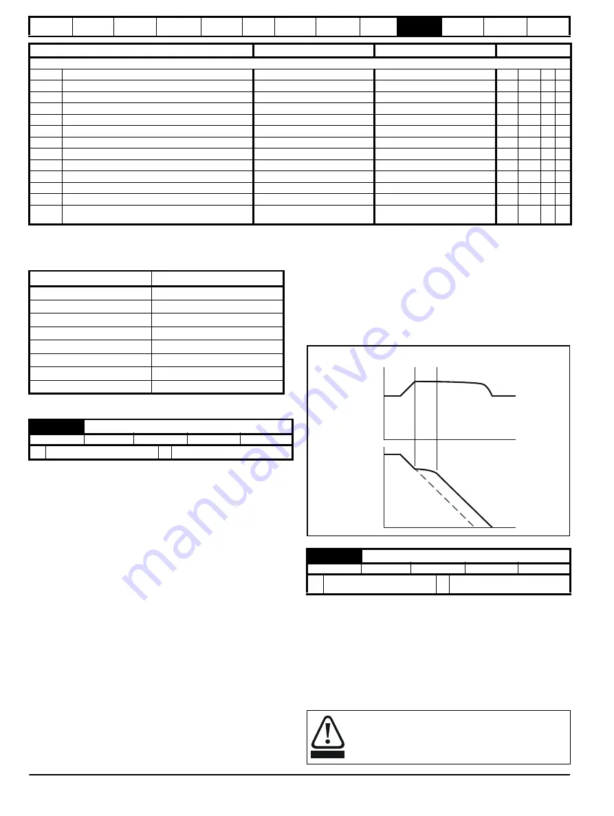
Controller
operating
DC-bus
voltage
Speed
Programmed
deceleration rate
Motor
speed
time
time
WARNING
Содержание Unidrive 1 Series
Страница 208: ......


