50
Epsilon EP-P Drive Reference Manual
www.controltechniques.com
Revision: A4
conservative approximate value should be used. If you enter an inertia value higher than the actual inertia, the resultant motor response will
tend to be more oscillatory.
Friction
This parameter is characterized in terms of the rate of friction increase per 100 motor RPM. If estimated, always use a conservative (less than
or equal to actual) estimate. If the friction is completely unknown, a value of zero should be used. A typical value used here is less than one
percent.
3.14.2 Low Pass Filter Group
The Low Pass Filter will reduce machine resonance due to mechanical coupling and other flexible drive/load components by filtering the
command generated by the velocity loop.
Low Pass Filter Enable Check Box
When this check box is selected it enables a Low Pass Filter to be applied to the output of the velocity command before the torque
compensator.
Low Pass Filter Frequency
This parameter defines the Low Pass Filter cut-off frequency. Signals exceeding this frequency will be filtered at a rate of 40 dB per decade.
The default value is 600 Hz.
3.14.3 Tuning Group
Response
The Response adjusts the velocity loop bandwidth with a range of 1 to 500 Hz. In general, it affects how quickly the drive will respond to
commands, load disturbances and velocity corrections. A good value to start with (the default) is 50 Hz. The maximum value recommended is
80 Hz.
Enable Feedforwards Check Box
When feedforwards are enabled, the accuracy of the Inertia and Friction parameters is very important. If the Inertia parameter is larger than the
actual inertia, the result could be a significant overshoot during ramping. If the Inertia parameter is smaller than the actual inertia, following
error during ramping will be reduced but not eliminated. If the Friction parameter is greater than the actual friction, it may result in velocity error
or instability. If the Friction parameter is less than the actual friction, velocity error will be reduced but not eliminated.
3.14.4 Position Error Integral Group
Time Constant Check Box
When this check box is selected it enables the Time Constant parameter.
Time Constant
Position Error Integral is a control term, which can be used to compensate for the continuous torque required to hold a vertical load against
gravity. It is also useful in low speed applications, which have high friction.
The user configures this control term using the “Position Error Integral Time Constant” parameter. This parameter determines how quickly the
drive will correct for in-position following error. The time constant is in milliseconds and defines how long it will take to decrease the following
error to 37 percent of the original value. In certain circumstances the value actually used by the drive will be greater than the value specified
here.
Min Time Constant = 1000/Response
For example, with “Response” set to 50, the minimum time constant value is 1000/50 = 20 msec.
3.15
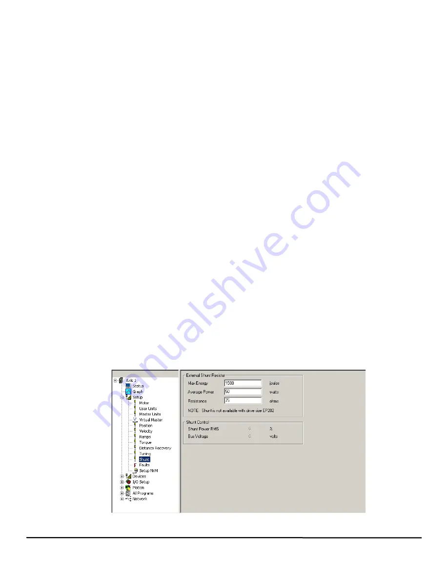
Shunt View
The Shunt view is used to configure the external shunt for the EP204, EP206, EP209 and EP216 drives.
Figure 52:
Shunt View
Содержание Epsilon EP-P
Страница 2: ......
Страница 14: ...xii Epsilon EP P Drive Reference Manual www controltechniques com Revision A4 Glossary 225 Index 231...
Страница 124: ...110 Epsilon EP P Drive Reference Manual www controltechniques com Revision A4...
Страница 200: ...186 Epsilon EP P Drive Reference Manual www controltechniques com Revision A4...
Страница 218: ...204 Epsilon EP P Drive Reference Manual www controltechniques com Revision A4...
Страница 238: ...224 Epsilon EP P Drive Reference Manual www controltechniques com Revision A4...
Страница 244: ...230 Epsilon EP P Drive Reference Manual www controltechniques com Revision A4...
Страница 247: ......


