REPAIR PROCEDURES
MANUAL
PVX Series Vane Pumps
“A” Design Series
Step-by-Step Guide to Troubleshooting and Repairing
Form No. 264728 Rev. 11/08
Страница 1: ...REPAIR PROCEDURES MANUAL PVX Series Vane Pumps A Design Series Step by Step Guide to Troubleshooting and Repairing PVX Series Vane Pumps Form No 264728 Rev 11 08...
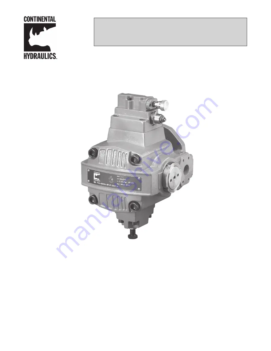
Страница 2: ...Voltage Design Letter PVX 75B _ _ _ _ P _ _ _ _ _ _ _ _ _ _ A Figure 2 MODEL CODE PVX 75B 00 00 P 00 00 00 00 00 A DATE P N V Pmax 3000 psi 210 bar IN3 REV CM3 U Model Code Figure 1 Thank you for choo...
Страница 3: ...tructions 20 21 Proper Setting of the Thrust Screw Adjustment Instructions 22 Adjustment Procedure Single Stage Compensator General 23 24 Adjustment Procedure Two Stage Compensator General 25 Multi Pr...
Страница 4: ...4 Port plate cover side 1 5 Roll pin 4 6 Thrust block 1 7 Bearing 2 8 Spacer ring 1 9 Pressure ring 1 10 Port plate body side 1 13 O ring ASA 031 ASA 035 2 14 O ring ASA 162 ASA 265 1 REFERENCE DESCR...
Страница 5: ...ure 1 2 Remove the four 4 socket hd cap screws on the cover by using the appropriate size Allen wrench Figure 2 Note For disassembling the larger pumps a great amount of torque will be needed to loose...
Страница 6: ...t by hand Figure 4 NOTE When disassembling a PVX 20 thru 75 pump please pay close attention not to loosen the ratio valve cartridge that is located in the cover and the ratio valve sealing assembly th...
Страница 7: ...r is over the bias piston or the smaller piston opposite the control piston Carefully remove the bias piston ensuring that the bias piston and the piston bore are not scratched or nicked Figure 10 11...
Страница 8: ...seal take a round head punch and carefully tap out from the cover side of the pump Remove the shaft seal Figure 17 18 After the pump has been completely disassembled all parts must be thoroughly clea...
Страница 9: ...ry depending on pump model 22 4 3 2 8 9 10 15 14 16 17 6 18 1 21 20 19 PVX 20 36 Torque to 1800 lb in Torque to 204 Nm Torque to 850 lb in Torque to 96 Nm Torque to 850 lb in Torque to 96 Nm Torque to...
Страница 10: ...Figure 3 NOTE It is recommended that a guide tool be used to properly install the bearings in the bores After the bearing is installed make sure the bearing is flush to 0 020 0 5 mm below the machined...
Страница 11: ...p The arrow on the pump can be found below the open segment for the control piston on the pump body Both arrows must point in the same direction All PVX pumps operate in a clockwise only direction of...
Страница 12: ...e body by using an Allen head wrench For PVX 20 thru 75 pumps prior to installing the thrust screw assembly lightly coat the bearing surface on the thrust block assembly with clean hydraulic fluid Fig...
Страница 13: ...of the pressure ring Figure 15 15a Make sure that the direction of the rounded vane tips matches the direction of pump rotation The pump rotation is shown on the pump body and the port plates Make sur...
Страница 14: ...rt O ring onto the body pilot bore A minimum amount of grease or petroleum jelly may be used to hold the O ring in place while installing the cover Figure 19 19a For PVX 20 thru 75 pumps insert a seco...
Страница 15: ...ur 4 socket head cap screws with the appropriate Allen wrench or socket Torque the screws from the chart below Keep the mating surfaces of the pump body and cover free of oil dirt and or grease before...
Страница 16: ...ve the English value first followed by the metric equivelent in parenthesis Left PVX 8 11 15 Right PVX 20 thru 75 Disassembly Instructions 1 Remove the two 2 socket head cap screws attaching the press...
Страница 17: ...ator for the PVX 8 11 15 pumps has a shock clipper which is located on the side of the first stage body Remove the plug by using the appropriate Allen wrench Figure 6a 7 Remove the first stage adjustm...
Страница 18: ...and inserting the round end first Figure 1 2 Replace the O ring and the back up ring on the adjustment stem Figure 2 2a Replace the O ring on the adjustment housing Assemble the adjustment stem into t...
Страница 19: ...he poppet seat with the O ring and insert it into the second stage compensator body using a large screwdriver Avoid damaging any of the O ring sealing surfaces Torque to 168 in lbs 19 Nm Figure 7 8 Yo...
Страница 20: ...sure that all O rings are in place on the mating surface of the second stage body A minimum amount of grease or petroleum jelly may be used to retain the O rings during placement Figure 11 11a Mount t...