background image


2. Setup 


AIO-121602LN-USB, AIO-120802LN-USB 

11


2.


Setup 

This chapter explains how to set up this product. 

What is Setup? 

Setup means a series of steps to take before the product can be used. 
Different steps are required for software and hardware. 

Installing the driver 

This section enables you to prepare the software and hardware by operating in accordance with each 

step in this chapter using the bundled CD-ROM. Taking the following steps sets up the software and 
hardware. You can use the diagnosis program later to check whether the software and hardware function 

normally. 

Step 1 Setting the Hardware 

Step 2 Installing the Software 

Step 3 Installing the Hardware 

Step 4 Checking Operations with the Diagnosis Program 

Uninstall the driver and then set it up again if it cannot be set up properly. 


The following shows the basic flow for installing product. 


Setting Properties Using 
Device Manager 
  - Setting the Device 

Name. 

Page 13


Connecting the Product 
- Connecting the PC 

Installing the Software 
- API-USBP(WDM) 

Development Environment 

- C-LOGGER 

Page 16


Page 18


Содержание AIO-120802LN-USB

Страница 1: ...PC HELPER N Series for USB Multifunction DAQ Unit 16ch AI 2ch AO 16ch DIO AIO 121602LN USB Multifunction DAQ Unit 8ch AI 2ch AO 16ch DIO AIO 120802LN USB User s Guide CONTEC CO LTD ...

Страница 2: ...g items contact your retailer Product Configuration List Unit One of the following 1 AIO 121602LN USB AIO 120802LN USB USB cable 1 8m 1 USB cable attachment on the main unit s side For Mini B connector side 1 First step guide 1 I O connector AIO 121602LN USB 6 AIO 120802LN USB 5 Rubber feet 4 Magnet 2 CD ROM 1 API USBP WDM 1 Warranty Certificate 1 Serial number label 1 1 The CD ROM contains the dr...

Страница 3: ...ect to change without notice All relevant issues have been considered in the preparation of this document Should you notice an omission or any questionable item in this document please feel free to notify CONTEC CO LTD Regardless of the foregoing statement CONTEC assumes no responsibility for any errors that may appear in this document or for results obtained by the user as a result of using this ...

Страница 4: ... 8 Inspection 8 Storage 9 Disposal 9 2 SETUP 11 What is Setup 11 Installing the driver 11 Step 1 Setting the Hardware 12 Name of each parts 12 Step 2 Initializing the Software 13 Illustration of Menu Screen 13 Installation of API USBP WDM Development Environment 14 Installing C LOGGER 15 Step 3 Installing the Hardware 16 Connecting the Product 16 Setting with the Found New Hardware Wizard 17 Setti...

Страница 5: ...ction 41 Single ended Input 41 Differential Input 42 Analog Output Signal Connection 43 Connecting I O Signals 44 I O Circuit 44 Example of Connection 44 Counter signals and Control signals Connection 45 4 APPLICATION DEVELOPMENT 47 Reference to Online Help 47 Printing Function Reference 47 Sample Program 48 Distributing Developed Application 48 Use of utility program 49 Returning to Initial State...

Страница 6: ...nditions 81 2 Starting Stopping Operation 82 3 Monitoring the Status and Acquiring Data 82 4 Reset 83 Digital Input Function 84 Digital Output Function 85 7 ABOUT HARDWARE 87 Hardware specification 87 Physical dimensions 91 Block Diagram 92 Control Signal Timings 93 Control Signal Timings for Analog Input 93 Control Signal Timings for Analog Output 94 Control Signal Timings for Counter 95 About Ca...

Страница 7: ...vi AIO 121602LN USB AIO 120802LN USB ...

Страница 8: ...eight signals units Analog I O can be synchronized with an internal timer or external clock Analog I O can both be performed at fixed time intervals and synchronized with an external signal Digital filter function to prevent wrong recognition of external signal chattering is provided This product has analog input output control signal digital input signal and digital filter function to prevent it ...

Страница 9: ...og I O driver API USBP WDM makes it possible to create applications of Windows In addition a diagnostic program by which the operations of hardware can be checked is provided Supported to the data logger software C LOGGER Analog input only Supporting the data logger software C LOGGER that enables the graph display of recorded signal data file saving and dynamic transfer to the spreadsheet software...

Страница 10: ... product device apiusbp For more details on the supported OS applicable language and new information please visit the CONTEC s Web site Data Logger Software C LOGGER Stored on the bundled CD ROM driver library API USBP WDM C LOGGER is a data logger software program compatible with our analog I O products This program enables the graph display of recorded signal data zoom observation file saving an...

Страница 11: ...harge only when this device is returned freight prepaid with a copy of the original invoice and a Return Merchandise Authorization to the distributor or the CONTEC group office from which it was purchased This warranty is not applicable for scratches or normal wear but only for the electronic circuitry and original products The warranty is not applicable if the device has been tampered with or dam...

Страница 12: ...se this may malfunction overheat or cause a failure If the terminals are touched by someone s hands clean the terminals with industrial alcohol Do not close the ventilation hole s of this product by for example placing an object This may cause overheating malfunction and or failure of the product Do not touch the external connector when the power is on Otherwise this may malfunction overheat cause...

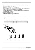
Страница 13: ...1cm from the product while leaving it open and then close it Regarding VCCI Class A Notice This product has acquired the above mentioned standard However a sufficient margin may not be secured for the standard In this case use a ferrite core TDK ZCAT 3035 1330 for the USB cable When attaching the ferrite core coil it around twice near the connector 1cm from the product while leaving it open and th...

Страница 14: ... 15 of the FCC Rules These limits are designed to provide reasonable protection against harmful interference when the equipment is operated in a commercial environment This equipment generates uses and can radiate radio frequency energy and if not installed and used in accordance with the instruction manual may cause harmful interference to radio communications Operation of this equipment in a res...

Страница 15: ...ause a failure Operating temperature 0 50 C Humidity 10 90 RH No condensation Corrosive gases None Floating dust particles Not to be excessive Inspection Inspect the product periodically as follows to use it safely Check that the ventilation slit has no obstruction and has no dust or foreign matter adhering Moreover if there is the slit on the case side please confirm it to the slit similarly CAUT...

Страница 16: ...duct in the storage bag 2 Wrap it in the packing material and then put it in the box 3 Store the package at room temperature at a place free from direct sunlight moisture shock vibration magnetism and static electricity Disposal When disposing of the product follow the disposal procedures stipulated under the relevant laws and municipal ordinances ...

Страница 17: ...1 Before Using the Product 10 AIO 121602LN USB AIO 120802LN USB ...

Страница 18: ...wing steps sets up the software and hardware You can use the diagnosis program later to check whether the software and hardware function normally Step 1 Setting the Hardware Step 2 Installing the Software Step 3 Installing the Hardware Step 4 Checking Operations with the Diagnosis Program Uninstall the driver and then set it up again if it cannot be set up properly The following shows the basic fl...

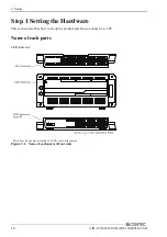
Страница 19: ... USB Step 1 Setting the Hardware This section describes how to set up the product and how to connect it to a PC Name of each parts LED indicator The above figure has installed the USB cable attachment Figure 2 1 Name of each parts Front side ...

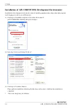
Страница 20: ...XP please log on as Administrator authorized account before proceeding to the following steps Illustration of Menu Screen Points Please set up the supplied CD ROM if it has not been set up The menu starts automatically If the menu do not start launch X AUTORUN EXE X CD ROM drive from Run in Start menu The screen design may be different Install C LOGGER Refer to the content of CD ROM Install Develo...

Страница 21: ...lp and sample program in all language in order to use API function 1 Clicking on Install Development or Execution Environment API USBP WDM Installer dialog box displays 2 Selecting Advanced Analog I O driver 3 Clicking on Continue Button Please perform installation following the directions on the screen And thus the installation is completed The screen design may be different ...

Страница 22: ...he data collection software 1 Clicking on C LOGER Choose Setup Language dialog box displays 2 Selecting English 3 Clicking on OK Button Please perform installation following the directions on the screen And thus the installation is completed The screen design may be different ...

Страница 23: ...this product 2 When the PC has been up and running plug the USB interface connector to a USB port in the PC The converter can also be connected to the PC via a USB hub of this product Figure 2 2 Connecting the PC 3 USB cable can be attached firmly to the main unit by using a USB cable attachment Figure 2 3 Attaching a USB Attachment The USB cable attachment cannot be used excluding an attached cab...

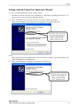
Страница 24: ...list or specific location then click on the Next button Detect setup information from supplied CD automatically for installing USB driver Point Please specify the path for supplied CD as follows in the case of failure in detecting automatically X INF WDM AIO X CD ROM drive 3 Click on Finish button to complete the installation of USB driver The name of the connected product will be displayed AIO 12...

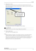
Страница 25: ...n Device Manager and set properties 1 Starting Device Manager From Start menu click on Settings Control Panel System and then click on Device Manager button in Hardware tab In the case of Windows 98 Me Right click on My Computer and select Properties to start device manager The name of the connected product will be displayed AIO 121602LN USB AIO 120802LN USB ...

Страница 26: ...ust be performed 3 Clicking on OK button Device name is set by clicking OK button Points When the application developed by users is running on another PC please perform foregoing operation on the target computer No need to install software introduced on next page Please use the device name specified in last step for initialization function when initialization is performed using API function When r...

Страница 27: ...heck Method To check the analog I O data use the loopback connection on the board to directly connect the analog output channel 0 to an analog input or connect to an external signal source No external connection is required if using loopback to check the I O The figure below shows an example of checking by connecting to an external signal The example is for channel 0 on the product Connection diag...

Страница 28: ... Starting the Diagnosis Program Click Diagnosis on the Properties page to start the diagnosis program The name of the connected product will be displayed AIO 121602LN USB AIO 120802LN USB The name of the connected product will be displayed AIO 121602LN USB AIO 120802LN USB ...

Страница 29: ...r square wave as the output data Digital I O In the diagnosis program digital input output is fixed to 8 points each The upper row of circular lamps indicates the digital input states Red indicates the bit is ON and brown indicates OFF Clicking the lower row of switches turns the digital output bits ON or OFF Counter input Selecting a counter channel displays the count value and state of that coun...

Страница 30: ... report text file 2 The diagnosis report contains the following data Version of OS Device Information File Information Initialization interrupts I O state for each channel Execution time measurement Clicking Execution Time Measurement runs the program to measure API function execution speed The operation of this program is explained in API function Execution Speed Measurement Program in Chapter 4 ...

Страница 31: ...e input check by connecting a battery or similar if you do not have any other suitable signal source Also check that connecting to analog ground reads correctly as 0V The diagnostic program works correctly but the application program does not The diagnostic program uses the API TOOL functions If the diagnostic program works correctly other applications should work correctly also If you have a prob...

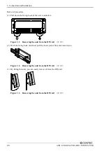
Страница 32: ... Push the fixing hook up using a slotted screwdriver to make it unlockable Figure 3 1 Mounting on a DIN Rail 1 3 2 Hook the product from the upper part of the DIN rail and press the lower part on to the DIN rail Figure 3 1 Mounting on a DIN Rail 2 3 3 Push the fixing hook up using a slotted screwdriver to make it lockable Figure 3 1 Mounting on a DIN Rail 3 3 ...

Страница 33: ... the unit to unlock it Figure 3 2 Removing the unit from the DIN rail 1 3 2 With the fixing hook unlocked pull the lower part of this unit toward you Figure 3 2 Removing the unit from the DIN rail 2 3 3 By lifting this unit you can easily remove it from the DIN rail Figure 3 2 Removing the unit from the DIN rail 3 3 ...

Страница 34: ...the product on the desktop mount it on a horizontal platform The rubber feet can be mounted in their mounting holes as shown in the following figure Figure 3 3 Mounting the rubber feet Wall Installation To mount the product on the wall purchase the commercially available screw fitting for φ3 5 separately Figure 3 4 Wall Installation ...

Страница 35: ...ed while mounted on the steel surface the surface paint may be scratched When using the magnet stack connection is not possible Mounting removing the magnet To mount the magnet press down the entire length of the magnet into its mounting hole while pushing the magnet in the direction of arrow 1 Next slide the magnet in the direction of arrow 2 to fix it in position Figure 3 5 Mounting the magnet T...

Страница 36: ...IO 121602LN USB AIO 120802LN USB 29 Mounting onto the steel wall Mount the product directly onto the steel wall Pull it gently after mounting to confirm that it will not drop off from the body Figure 3 7 Mounting onto the steel wall ...

Страница 37: ...n usage such as inadequate heat dissipation DIN rail fixation Vertical installation Horizontal installation Installation on a ceiling Figure 3 8 DIN rail fixation Screws magnet fixation Vertical installation Horizontal installation Installation on a ceiling Figure 3 9 Screws magnet fixation When using the product in a high temperature environment cool it by blowing air even when the temperature is...

Страница 38: ... between the system unit and any surrounding objects Secure a distance of at least 50mm between the top of the main unit single use and any surrounding objects Do not locate the unit in a fully enclosed housing Figure 3 10 Spacing between the unit and any surrounding objects ...

Страница 39: ...n wiring the unit strip off approximately 7 mm of the covering for the cable and insert the bare wire by pressing the orange button on the connector plug Releasing the orange button after the wire is inserted fixes the cable Compatible wires are AWG 28 16 Figure 3 11 Connecting an Interface Connector and Connectors That Can Be Used Removing the connector plug by grasping the cable can break the wi...

Страница 40: ...Output 05 AI06 Analog Input 06 AISTP AI External Stop Trigger Input DIO06 Digital Input Output 06 AI07 Analog Input 07 AICLK AI External Sampling Clock Input DIO07 Digital Input Output 07 AGND Analog Ground for AI DGND DigitalGround DGND DigitalGround AI08 Analog Input 08 DGND DigitalGround DIO08 Digital Input Output 08 AI09 Analog Input 09 AOSTA AO External Start Trigger Input DIO09 Digital Input...

Страница 41: ...lock input for analog input AO External Start Trigger Input External trigger input for starting analog output sampling AO External Stop Trigger Input External trigger input for stopping analog output sampling AO External Sampling Clock Input External sampling clock input for analog output Digital Input Output 00 Digital Input Output 15 Digital Input Output signal Counter Gate Control Input Gate co...

Страница 42: ...Digital Input Output 06 AI07 Analog Input 03 AICLK AI External Sampling Clock Input DIO07 Digital Input Output 07 AGND Analog Ground for AI DGND DigitalGround DGND DigitalGround AI08 Analog Input 04 DGND DigitalGround DIO08 Digital Input Output 08 AI09 Analog Input 04 AOSTA AO External Start Trigger Input DIO09 Digital Input Output 09 AI10 Analog Input 05 AOSTP AO External Stop Trigger Input DIO10...

Страница 43: ...lock input for analog input AO External Start Trigger Input External trigger input for starting analog output sampling AO External Stop Trigger Input External trigger input for stopping analog output sampling AO External Sampling Clock Input External sampling clock input for analog output Digital Input Output 00 Digital Input Output 15 Digital input Output signal Counter Gate Control Input Gate co...

Страница 44: ...ut 04 AI05 Analog Input 05 CNT G Counter Gate Control Input DIO05 Digital Input Output 05 AI06 Analog Input 06 RES Reserved DIO06 Digital Input Output 06 AI07 Analog Input 07 CNT C Counter Up Clock Input DIO07 Digital Input Output 07 AGND Analog Ground for AI DGND DigitalGround DGND DigitalGround AO00 Analog Output 00 DIO08 Digital Input Output 08 AGND Analog Ground for AO DIO09 Digital Input Outp...

Страница 45: ...ock input for analog input AO External Start Trigger Input External trigger input for starting analog output sampling AO External Stop Trigger Input External trigger input for stopping analog output sampling AO External Sampling Clock Input External sampling clock input for analog output Digital Input Output 00 Digital Input Output 15 Digital input Output signal Digital Output00 Digital Output 03 ...

Страница 46: ...ut 04 AI05 Analog Input 02 CNT G Counter Gate Control Input DIO05 Digital Input Output 05 AI06 Analog Input 03 RES Reserved DIO06 Digital Input Output 06 AI07 Analog Input 03 CNT C Counter Up Clock Input DIO07 Digital Input Output 07 AGND Analog Ground for AI DGND DigitalGround DGND DigitalGround AO00 Analog Output 00 DIO08 Digital Input Output 08 AGND Analog Ground for AO DIO09 Digital Input Outp...

Страница 47: ...ck Input External sampling clock input for analog input AO External Start Trigger Input External trigger input for starting analog output sampling AO External Stop Trigger Input External trigger input for stopping analog output sampling AO External Sampling Clock Input External sampling clock input for analog output Digital Input Output 00 Digital Input Output 15 Digital input Output signal Counte...

Страница 48: ...Hz signals the signal may affect the cross talk noise between channels If the unit and the signal source receive noise or the distance between the unit and the signal source is too long data may not be input properly An input analog signal should not exceed the maximum input voltage relate to the product analog ground If it exceeds the maximum voltage the unit may be damaged Connect all the unused...

Страница 49: ...etween channels When the analog ground is not connected the conversion data is not determined If the unit and the signal source receive noise or the distance between the unit and the signal source is too long data may not be input properly An input analog signal should not exceed the maximum input voltage relate to the unit analog ground If it exceeds the maximum voltage the unit may be damaged Co...

Страница 50: ...ce connector analog output connect the core wire to the signal line and connect the shielding to ground Figure 3 21 Analog Output Connection Shielded Cable If this product or the connected wire receives noise or the distance between this product and the target is long data may not be outputted properly For analog output signal the current capacity is 3mA Max Check the specification of the connecte...

Страница 51: ...Connection When switch is ON the corresponding bit is 0 When switch is OFF in contrast the corresponding bit is 1 When 1 is output to a relevant bit the corresponding LED comes on When 0 is output to the bit in contrast the LED goes out Figure 3 23 Connection Example Using DIO00 for Input and DIO08 for Output Take care not to short the outputs to digital ground as this may cause a fault 10kΩ Vcc U...

Страница 52: ...validate or invalidate the input of an external clock for the counter This function enables the control of an external clock input for the counter The external clock for the counter is effective when input is High and invalid when input is Low If unconnected it is a pull up in this product and remains High Therefore the external clock for the counter is effective when the counter gate control inpu...

Страница 53: ...3 Connection and Installation 46 AIO 121602LN USB AIO 120802LN USB ...

Страница 54: ...tion development such as function reference is provided in API USBP WDM Help Detailed introduction to search method for help should be found from How to navigate Help in the help Printing Function Reference Clicking on Print button from online help prints the page being displayed It can be printed entirely as follows in the case of referencing to printing function As figure shown on the right sele...

Страница 55: ...is Program Files CONTEC Sample programs in all language are provided here To run a sample program click on Programs CONTEC API USBP WDM AIO Sample Name from Start menu Distributing Developed Application Please distribute the developed application with USB driver in supplied CD ROM Created application including driver can be freely distributed ...

Страница 56: ...n Measure tool from CONTEC DIAGNOSIS PROGRAM Step to use 1 Select the device to be measured from the device list 2 Measure the executive speed of a function by clicking the button with the function name Select the number of channels for conversion from the list for AioMultiAi and AioMultiAo Input the size of data to be transferred for AioGetAiSamplingData and AioSetAoSamplingData Set the transfer ...

Страница 57: ...data of the memory is acquired Data in the FIFO memory can be confirmed visually The number of channels used the internal external clock the conversion speed and the sampling frequency at which an event generates can be set Since the notification of a sampling clock error event is sent please make use of it for the conversion spec measurement under various conversion conditions 256K The name of th...

Страница 58: ... in FIFO is It is conversion data taken in the memory This can be visually checked in a memory image Event generation sampling frequency When the number of input sampling in FIFO reaches this frequency the event generates Total input sampling frequency It is the total number of samplings for application in the memory Measurement may stop by the following errors Sampling clock error It means that t...

Страница 59: ...ating an event and number of samples to load at each event can be specified As an event is also generated if a sampling clock error occurs you can use the utility to test the conversion operation under a range of different conditions Step to use 1 Use the combo box at the top left of the window to select the device name of the device to use then click the Set button 2 Specify the conversion condit...

Страница 60: ...count for triggering event An event is triggered when the number of samples remaining in the FIFO reaches the specified value Number of samples to load The number of output data values samples to load at each event The Measuring will stop when this error as follows Sampling clock error When the application is measuring with internal clock sampling clock is too fast to process When the application ...

Страница 61: ... return to initial state and perform installation again when the operation is losing stabilization 1 Deleting Device form Device Manager 2 Drawing USB cable from a PC 3 Uninstalling Driver Select CONTEC API AIO WDM driver from My Computer Control Panel Add Remove Programs 4 Restarting The name of the connected product will be displayed AIO 121602LN USB AIO 120802LN USB ...

Страница 62: ... The program is stored on the attached CD ROM Driver Library API USBP WDM C LOGGER offers the following functions Sampling and displaying data with high speed Supporting plural windows Sending to excel with high speed Supporting 2 data binary and csv forms Setting acquirement conditions easily with wizard Operating intuitively with file viewer and property viewer Saving to file automatically for l...

Страница 63: ...5 About C LOGGER 56 AIO 121602LN USB AIO 120802LN USB ...

Страница 64: ... data according to the resolution and stores it in memory You can set a variety of conditions for analog input including the input channel sampling period and sampling start stop conditions Analog input processes are classified as follows 1 Setting the Conversion Conditions Clock Start Condition Stop Condition Event Resolution Input Mode Channel Start Stop 2 Starting Stopping Operation Status Memo...

Страница 65: ...Input Mode indicates the method of connecting analog input signals The input modes available are single ended input and differential input The single ended input mode is suitable for the environment in which the potential difference between the signal source and ground and noise components can be ignored For the environment in which they cannot be ignored the differential input mode is suitable Th...

Страница 66: ...rformed consecutively starting from channel 0 Software setup is not required as this board uses a fixed channel conversion priority Range Range means the range of voltages at which analog input can be performed Software setup of the range is not required as this board uses a fixed range of voltages AIO 121602LN USB 10V 5V 2 5V 0 10V AIO 120802LN USB 10V 5V 2 5V 0 10V ...

Страница 67: ... memory on the device itself or in the driver The device buffer can operate as FIFO or ring memory The application calls an API function at an appropriate timing and fetches the conversion data from the device buffer The device buffer mode provides function that allows the number of items of conversion data using the number of sampling times as a unit to obtain the number of items of conversion da...

Страница 68: ... in which the memory has stored a fixed amount of data or in which the memory has become full The FIFO memory is used to obtain all input data from analog input in a short or infinite period of time Ring format In the ring format the memory contains storage areas arranged in a ring Input data items are written to the memory sequentially When it stores data exceeding the limit it overwrites the are...

Страница 69: ...hich case the conversion is terminated by the software abort command Input data items are stored to the memory sequentially The repetition state can be subject to status monitoring and application notification Clock The sampling clock controls the sampling frequency You can select both the internal sampling clock and external sampling clock Internal sampling clock The clock signal from the on boar...

Страница 70: ...at the level comparison condition is satisfied in the rising direction The start condition is satisfied when the analog signal at the specified channel passes the comparison level in the rising direction Input data items are stored to memory starting with those at solid dots The above sketch shows that the level comparison condition is satisfied in the falling direction The start condition is sati...

Страница 71: ...omparison condition is satisfied in the rising direction The stop condition is satisfied when the analog signal at the specified channel passes the comparison level in the rising direction Input data items are stored to memory ending until those at solid dots The above sketch shows that the level comparison condition is satisfied in the falling direction The stop condition is satisfied when the an...

Страница 72: ...ration event This event occurs when the entire operation including repetitions is completed Stored specified sampling times event This event occurs when sampling has been performed for the number of times set by software This event can only be used in device buffer mode Overflow event This event occurs at an attempt to store input data with the memory full Sampling clock error event This event occ...

Страница 73: ...cified sampling data stored This status is set to ON when input data stored in memory has reached the amount corresponding to the preset number of times of sampling If the memory format is FIFO the status is set to OFF when the amount of input data in the memory falls below the value corresponding to the preset number of times of sampling as data is acquired Once the status is set to ON when the m...

Страница 74: ...ut data is acquired differently depending on the memory format used Data acquisition in FIFO format When FIFO memory is used the oldest data is always read first The following sketch shows an image of data acquisition in FIFO format When data is acquired from the memory the free memory space increases by that data size When data is acquired next the oldest one of the existing data items is taken f...

Страница 75: ... The following sketch shows an image of data acquisition in ring format The sampling count obtained is always the number of times of sampling for up to the latest data shaded portion below The larger the number of samples taken the older the data item acquired first As the ring memory retains data even after that data is acquired you can fetch the same data any number of times ...

Страница 76: ...ion between AD conversion data and voltage Voltage Conversion data 12 bit 9 995V 4095 0 005V 2049 0V 2048 0 005V 2047 10 000V 0 Ex When input data 3072 is input at a resolution of 12 bit in the 10V range Voltage 3072 x 10 10 4096 10 5 0 0 10V range The following table shows the relation between AD conversion data and voltage Voltage Conversion data 12 bit 9 998V 4095 5 002V 2049 5 000V 2048 4 998V...

Страница 77: ...d AD conversion error status Memory This can only be used when the transfer mode is set to device buffer mode This command resets the following memory related states Resets the conversion data in memory Resets the repeat count to 0 Resets the sampling count to 0 when a stop trigger is input Resets the buffer overflow status Resets the status information for the specified data save count ...

Страница 78: ...ng the output channel sampling period and sampling start stop conditions Analog output processes are classified as follows 1 Setting the Conversion Conditions Clock Start Condition Stop Condition Event Resolution Channel Range Output data Data transfer method Memory format Repeat Setting data Status Sampling Start Stop 2 Starting Stopping Operation 3 Monitoring the Status and Acquiring Data Status...

Страница 79: ...ts If the device has a resolution of 12bit it is 10 4096 2 44mV instead AIO 121602LN USB The resolution is 12bit AIO 120802LN USB The resolution is 12bit Channel Channel represents each point of analog output For individual channel numbers see How to connect the connectors to Connector Pin Assignment in Chapter 3 External Connection You can specify an arbitrary number of points of analog output by...

Страница 80: ...0 10 2662 4 The value that can be set as output data at this time is an integer Select 2662 or 2663 as the output data The analog signal corresponding to the output data contains an error as follows Output data 2662 converted to 2 9980 V Output data 2663 converted to 3 0029 V This error is a consequential error occurring when output data is obtained from an expected analog value 0 10V range The ta...

Страница 81: ...ta is obtained from an expected analog value Data transfer method It is the device buffer mode which uses memory for conversion data storage either on the device or in the driver The application output data is first stored in the device buffer memory on the device itself or in the driver When conversion starts the device starts outputting the output data The device buffer can operate as FIFO or RI...

Страница 82: ...like that shown below When using FIFO format writing of conversion data to memory is always performed from after the most recent data and DA conversion is performed on the oldest data in memory You can write to memory during analog output operation An error occurs if the volume of data exceeds the memory size However this error does not stop analog output if it is in progress Ring format Use ring ...

Страница 83: ...channel output from multiple channels is also possible Repeat You can specify a repeat count to perform sampling for a specified number of times Memory must be set to ring format if a number of repetitions is to be specified The number of repetitions cannot be specified for FIFO memory format The number of repetitions is set by software and sampling is repeated for the specified number of times Yo...

Страница 84: ...ion channels The procedure for setting the conversion data is different depending on the memory format being used Procedure for FIFO format When using FIFO format setting data to memory is always performed from the most recent data New data can be added during conversion Procedure for RING format When using ring format a ring memory area large enough for the data to be set is reserved Data cannot ...

Страница 85: ...rising edge or falling edge is input from the external control signal Stop Condition The condition for controlling the stop of sampling can be selected from among the last sampling count an external trigger software The product stops sampling whenever an error occurs irrespective of the stop condition setting Last sampling count The product stops sampling after storing input data to memory for the...

Страница 86: ...You can use a software command to check the status of analog output operation and of the output data stored in memory Status The current state of the device can be checked by obtaining the device status The following types of device status are available Device operating The device operating status remains ON after the execution of the sampling start command until the product completes conversion a...

Страница 87: ...d by the software command This command can only be used in device buffer mode 4 Reset Various states can be reset by executing the following reset commands Status This command resets the sampling clock error status and AD conversion error status Memory This can only be used when the transfer mode is set to device buffer mode This command resets the following memory related states Resets the conver...

Страница 88: ...ws an example of using the compare count load function After the counter starts the first count match occurs when the count reaches 1000 When the count reaches 1000 the counter value at which the second compare count match is to occur 2000 is set This continues with the next value from the array being set each time a count match occurs After the final value from the array is loaded operation can s...

Страница 89: ...ile the counter is running Status The current state of the device can be checked by obtaining the device status The following types of device status are available Counter operating The device operating status is ON from the time the operation start command is executed until operation stops due to a stop command or error Compare count match The compare count match status turns ON when a count match...

Страница 90: ...2LN USB 83 4 Reset Various states can be reset by executing the following reset commands Counter reset Resets the counter This restores the counter to its state after power on Status Resets the compare count match status and overrun status ...

Страница 91: ...Individual input bits can be input in byte units When the number of input points of the device is 4 the individual input bits are arranged as shown below and the byte data to be input is a value between 0 and 15 depending on the states of the bits EX Input of bit 7 OFF bit 6 ON bit 5 OFF bit 4 ON bit 3 OFF bit 2 ON bit 1 OFF bit 0 ON Byte data 85 55H Digital filter A digital filter can be used on ...

Страница 92: ...bit can be changed to ON or OFF by specifying the bit and setting it to 1 or 0 Output in Bytes Individual output bits can be output in byte units When the number of output points of the device is 4 the individual output bits are arranged as shown below and byte data to be output is a value between 0 and 15 Ex Output of bit 7 ON bit 6 OFF bit 5 ON bit 4 OFF bit3 ON bit 2 OFF bit 1 ON and bit 0 OFF ...

Страница 93: ...6 Function 86 AIO 121602LN USB AIO 120802LN USB ...

Страница 94: ...art signal TTL level Rising or falling edge can be selected by software External stop signal TTL level Rising or falling edge can be selected by software External clock signal TTL level Rising or falling edge can be selected by software Analog output Isolated specification Un Isolated Number of output channels 2ch Output range Bipolar 10V 5V or Unipolar 0 10V 0 5V Output current ability 3mA Output...

Страница 95: ...ber of terminals used at the same time 127 terminals Max 5 Power consumption Max 5VDC 450mA Operating condition 6 0 50 C 10 90 RH No condensation Physical dimensions mm 180 L x 140 D x 34 H No protrusions Weight 300g Attached cable length USB Cable 1 8m 1 A linearity error approximately 0 1 of full range may occur when operated at 0ºC or 50ºC ambient temperature 2 The required time is indicated in...

Страница 96: ...Rising or falling edge can be selected by software External stop signal TTL level Rising or falling edge can be selected by software External clock signal TTL level Rising or falling edge can be selected by software Analog output Isolated specification Un Isolated Number of output channels 2ch Output range Bipolar 10V 5V or Unipolar 0 10V 0 5V Output current ability 3mA Output impedance 1Ω or less...

Страница 97: ...ber of terminals used at the same time 127 terminals Max 5 Power consumption Max 5VDC 450mA Operating condition 6 0 50 C 10 90 RH No condensation Physical dimensions mm 180 L x 140 D x 34 H No protrusions Weight 300g Attached cable length USB Cable 1 8m 1 A linearity error approximately 0 1 of full range may occur when operated at 0ºC or 50ºC ambient temperature 2 The required time is indicated in...

Страница 98: ...7 About Hardware AIO 121602LN USB AIO 120802LN USB 91 Physical dimensions Figure 7 1 Physical dimensions AIO 121602LN USB Figure 7 2 Physical dimensions AIO 120802LN USB ...

Страница 99: ...7 About Hardware 92 AIO 121602LN USB AIO 120802LN USB Block Diagram Figure 7 3 Block Diagram AIO 121602LN USB Figure 7 4 Block Diagram AIO 120802LN USB ...

Страница 100: ...eter Symbol Time Unit Delay time from external sampling clock to first A D start pulse tDEC 100 nsec Set up time of sampling start Rising edge tSRS 100 nsec Hold time of sampling start Rising edge tHRS 100 nsec Set up time of sampling start Falling edge tSFS 100 nsec Hold time of sampling start Falling edge tHFS 100 nsec Set up time of sampling stop Rising edge tSRP 100 nsec Hold time of sampling ...

Страница 101: ...g time tWS 12000 nsec Set up time of sampling start Rising edge tSRS 100 nsec Hold time of sampling start Rising edge tHRS 100 nsec Set up time of sampling start Falling edge tSFS 100 nsec Hold time of sampling start Falling edge tHFS 100 nsec Set up time of sampling stop Rising edge tSRP 100 nsec Hold time of sampling stop Rising edge tHRP 100 nsec Set up time of sampling stop Falling edge tSFP 1...

Страница 102: ...Timing Chart of Counter Input Signal Figure 7 12 Timing Chart of Counter Output Signal Pulse output Table 7 5 Control Signal Timings Parameter Symbol Time Unit Set up time of counter input Rising edge tSRC 100 nsec Hold time of sampling start Rising edge tHRC 100 nsec Pulse width of counter output signal tPSC 1000 nsec The times listed in Table 7 5 are for standard operating conditions CAUTION ...

Страница 103: ...input has 12 bit resolution use a reference voltage generator with a precision of at least 4 digits after the decimal point Calibrate one channel only for each range that you use This product can calibrate only gain Analog output calibration Analog output calibration requires a digital multimeter As the analog output has 12 bit resolution use a multimeter with a precision of at least 4 digits afte...

Страница 104: ......

Страница 105: ...wa ku Osaka 555 0025 Japan Japanese http www contec co jp English http www contec com Chinese http www contec com cn No part of this document may be copied or reproduced in any form by any means without prior written consent of CONTEC CO LTD 09062013 09012011 Management No NA90061 09062013_rev3 Parts No LYMZ473 ...

Отзывы: