OPERATING & INSTALLATION INSTRUCTION 2-POST-LIFT
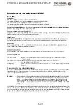
Description of the main board SGMX2
for EL-lifts
Overview:
The lift is equipped with an electronic control board.
The upper and lower limits can be adjusted to required circumstances.
The stored data can be adjusted to required circumstances.
The stored data is permanent and will not be lost when there is no power.
During the first installation of the lift, it is necessary to check the adjustment of the upper and lower
limits. If necessary, they have to be adjusted.
Required adjustments during installation:
Adjustment of lower and upper limits. Synchronisation of both carriages. Adjustment of the safety Stop when
lowering at a height of min. 200 mm above the ground.
Safety stop:
When lowering the lift, the carriages stop at the programmed point. After pushing the down button agains,
the carriages continue to the lower limit. You can hear the auditible warning noise during this operation.
Attention!
During programming the lift, the automatic limits do not work. –danger of collision in the upper and lower
limits-. Take care of approx. 10 mm overrun.
Initial installation:
Due to different local requirements and individual wishes, the different limits must be programmed.
Standard adjustments:
The lower limit:
Between the lowest point of the arm and the ground, there should be at least
10 mm of space.
The upper limit: Between the base plate and the lowest point of ther arm, there should be
A max. difference of 1900 mm.
Safety stop:
There should be a minimum of 200 mm between the lowest point of the arm and the
ground.
Preparation for the initial installation:
During the initial installation of the arms, or after repair, these should be conducted approx. 10 mm over the
lowest position as in the normal case. The lower position drive can be carefully followed with the lever
up/down in twice or indiviudal drive.
Notice:
The potentiometers are protected against mechanical breakage by means of a mechanical
end stop. It is possible, that the lower limit cannot be reached by using the motor. In this
case, the potentiometer has to be dismounted and the carriage should be lwoered by
turning the pulley on top of the lift. When reaching the lower limit of the carriage, turn the
potentiometer clockwise until you reach the mechanical end stop. After that turn it back half
a turn.
In the lower lifting carriage position the path transitter pinion when unlocked is turned clockwise (seen from
above) until it reaches the mechanical Stopp, then turned back half a turn. With light pressure it will then
return to the locked position and the M6 safety screw of the path transmitter mounting is again secured.
Make sure there is an undamaged spring wahser under the screw head.
Page 45
Содержание 2.25 EMC
Страница 66: ...OPERATING INSTALLATION INSTRUCTION 2 POST LIFT Electric diagram for chain lifts H264 H265 Page 66 ...
Страница 67: ...OPERATING INSTALLATION INSTRUCTION 2 POST LIFT Electric diagram H342 Page 67 ...
Страница 68: ...OPERATING INSTALLATION INSTRUCTION 2 POST LIFT Electric diagram H325 Page 68 ...
Страница 69: ...OPERATING INSTALLATION INSTRUCTION 2 POST LIFT Electric diagram with rotary reversing switch Page 69 ...
Страница 70: ...OPERATING INSTALLATION INSTRUCTION 2 POST LIFT Electric diagram with push button Page 70 ...
Страница 71: ...OPERATING INSTALLATION INSTRUCTION 2 POST LIFT Page 71 ...
Страница 72: ...OPERATING INSTALLATION INSTRUCTION 2 POST LIFT Page 72 ...
Страница 73: ...OPERATING INSTALLATION INSTRUCTION 2 POST LIFT Page 73 ...
Страница 74: ...OPERATING INSTALLATION INSTRUCTION 2 POST LIFT Page 74 ...
Страница 75: ...OPERATING INSTALLATION INSTRUCTION 2 POST LIFT Page 75 ...
Страница 76: ...OPERATING INSTALLATION INSTRUCTION 2 POST LIFT Page 76 ...
Страница 77: ...OPERATING INSTALLATION INSTRUCTION 2 POST LIFT Page 77 ...
Страница 78: ...OPERATING INSTALLATION INSTRUCTION 2 POST LIFT Page 78 ...
Страница 79: ...OPERATING INSTALLATION INSTRUCTION 2 POST LIFT Page 79 ...
Страница 80: ...OPERATING INSTALLATION INSTRUCTION 2 POST LIFT Page 80 ...

