


ES-U-1001-R10(R100) Premier Gold USB-RS232 Adapter cable Data Sheet
Version 1.1
Document Reference No.: CP_000057 Clearance No.: CP#047
Copyright © Connective Peripherals Pte Ltd
15
4
Connections
4.1
External Connectors
4.1.1
USB
The USB-U-1001 is a downstream USB 2.0 Device. A standard USB Series “A” connector is mounted
inside the USB-U-1001 to facilitate connection to an upstream USB Host or Hub.
Pin Number
Pin Type
Description
1
Power
VBUS – USB Power provided from upstream USB Host or Hub
2
Bidirectional D– = USB data signal, negative polarity
3
Bidirectional D+ = USB data signal, positive polarity
4
Ground
GND = USB signal ground
Shield
Case Ground Drain = typically connected to the host PC case
Table 3.1 USB "A" Receptacle Pin-Out
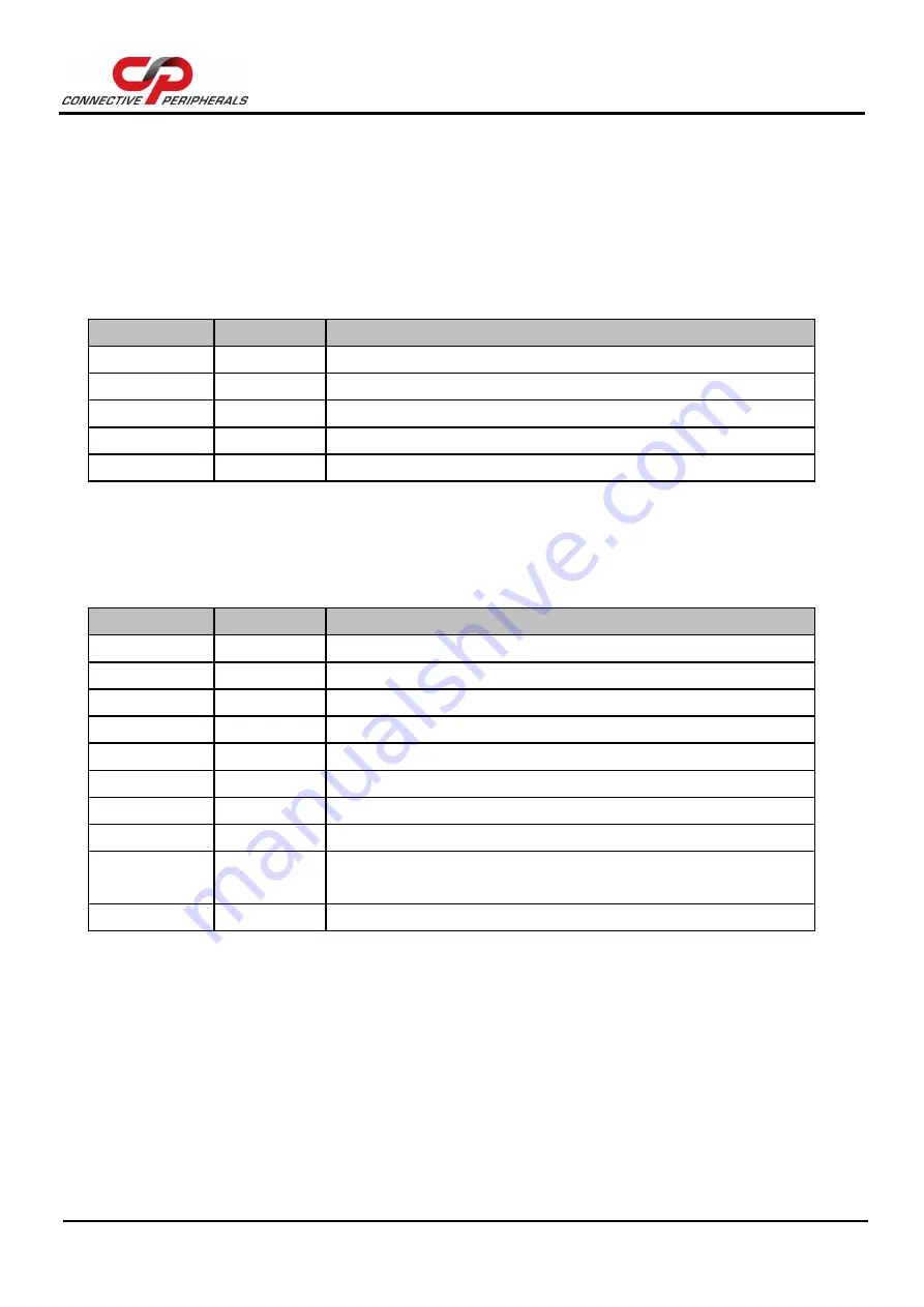
4.1.2
RS232
The RS232 port is configured as Data Terminal Equipment (DTE), with a 9-contact D-Sub Pin connector.
Pin assignments are according to TIA/EIA-574 which formally defines the assignments for a COM port
found on many personal computers.
Pin Number
Pin Type
Description
1
Input
DCD = Data Carrier Detect
2
Input
RXD = Receive Data
3
Output
TXD = Transmit Data
4
Output
DTR = Data Terminal Ready
5
Ground
GND = RS232 signal ground
6
Input
DSR = Data Set Ready
7
Output
RTS = Request To Send
8
Input
CTS = Clear To Send
9
Input /
Power
RI = Ring Indicator
Shield
Case Ground Drain = typically connected to the host PC case
Table 3.2 DE-9P RS232 Pin-Out


