
Copyright
©
2019
congatec
AG
JCWLm10
46/55
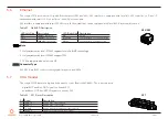
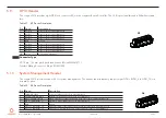
5.12
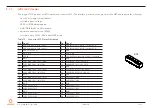
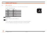
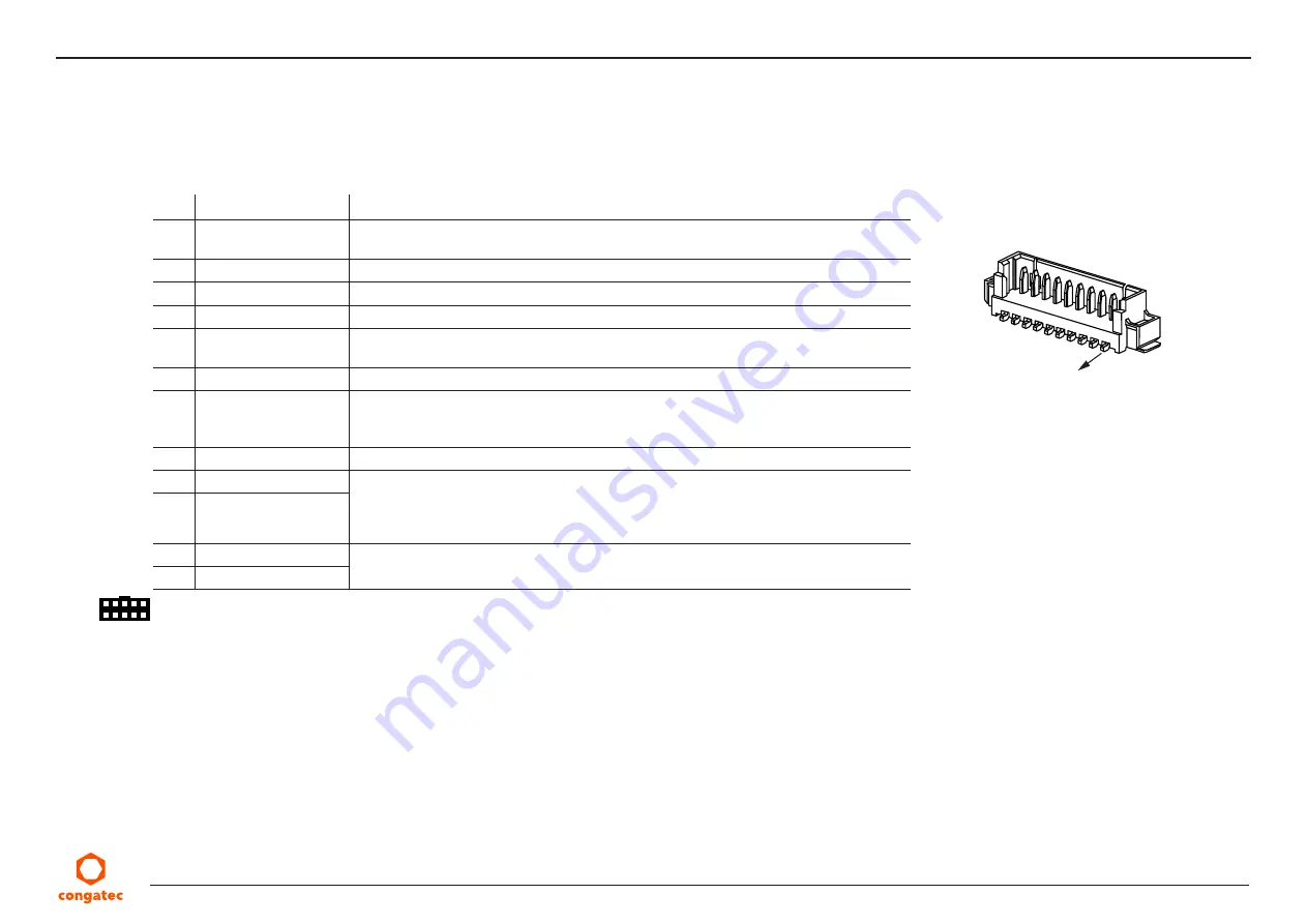
Front Panel Header
The conga-JC370 provides X4 for front panel features such as lid, sleep, reset and power buttons, as well as status LEDs.
Table 34 X4 Pinout Description
Pin Signal Name
Description
1
LID_BTN#
Active-low signal. Triggers sleep state, hibernation or shutdown (depends on OS
configuration)
2
GND
Ground
3
SLP_BTN#
Active-low signal. Triggers sleep state or hibernation (depends on OS configuration)
4
GND
Ground
5
RST_BTN#
Active-low signal. Triggers hard reset (system is not kept in reset when connected to
ground)
6
GND
Ground
7
PWR_BTN#
Active-low signal. Triggers power-up sequence. Pulse duration of ≥ 4 seconds triggers
forced shutdown. The cBC can also trigger signal depending on the BIOS settings (see
section 6.4.2 “Power Loss Control”)
8
GND
Ground
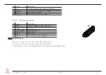
9
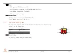
PWR_LED (anode)
For connecting bidirectional LEDs. The LEDs light when the system is powered on.
Main color (runtime state (S0)): pin 9 for anode and pin 10 for cathode
Alternate color (sleep state (S5)): pin 9 for cathode and pin 10 for anode
10
GND (cathode)
11
SATA_LED (anode)
LED indicates activity on the SATA, mSATA (X26) or M.2 Type M socket (X28) with SATA
SSD (onboard series resistor makes it possible to connect the LEDs directly to the pins)
12
SATA_ACT# (cathode)
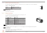
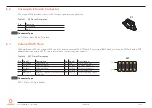
Connector Type
X4: 12-pin, 1.25 mm pitch (Molex 53398-1271)
Possible Mating Connector: Molex 0510211200
X4
pin 1


