


Copyright
©
2019
congatec
AG
JCWLm10
41/55
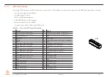
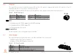
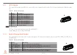
Pin Signal
Description
5
+5V
5 V power supply (protected by 500 mA resetable fuse)
6
+3.3V
3.3 V power supply for DMIC (protected by 500 mA resetable fuse)
7
DMIC_DATA
Serial data from digital MIC (3.3 V level signal)
8
GND
Ground reference for DMIC
9
DMIC_CLK
Digital MIC serial clock (3.3 V level signal)
Table 27 X32 Pinout Description
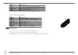
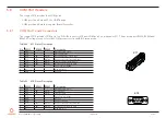
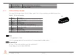
Pin Signal
Description
1
LINE2_R
Analog line / headphone output - right channel
2
LINE2_L
Analog line / headphone output - left channel
3
A_GND
Analog ground
4
SENSE_B_HPOUT
Headphone jack detection
5
SENSE_B_MIC
MIC jack detection
6
A_GND
Analog ground
7
MIC2_L
Analog microphone input - left channel
8
MIC2_R
Analog microphone input - right channel
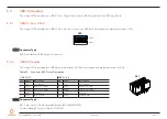
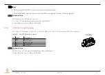
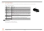
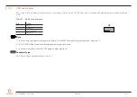
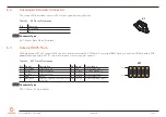
Connector Type
X31: 9-pin, 1.25 mm pitch picoblade header (Molex 0532610971)
X32: 8-pin, 1.25 mm pitch picoblade header (Molex 0533980871)
Possible Mating Connector: Molex 0510210900 for X31 and Molex 0510210800 for X32
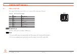
X32


