Power-On Diagnostics
17
Installing the Hardware
Power-On Diagnostics
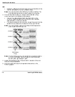
When you switch a VS1000 base unit on, it performs a self-diagnostic.
The results are displayed via the LED lights on the back panel. If the
unit is working correctly, the following events should take place:
1.
All LEDs should light up briefly, to show that they are working.
2.
Both 10Base-T lights should remain lit after the port LEDs go out,
while the unit establishes the Ethernet connection and polarity.
3.
If using 10Base-T cabling, the lower LED remains lit to indicate
that the Ethernet connection is established and polarity is correct.
4.
The Port 1 LED begins flashing, to indicate that the VS1000 is
waiting for the server to initiate VS-Link communications.
5.
The upper 10Base-T LED flashes briefly, as the server acquires
control of the VS1000.
6.
The port LEDs begin flashing in a “sweeping” sequence, to
indicate that the unit is operating normally.
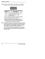
The following figures and tables illustrate LED patterns for
diagnosing hardware problems.
Table 4. 10Base-T LED Descriptions
LED Indicator
Description
Upper
Flashes
Briefly
During the power-on cycle (first few
seconds after the power is turned on),
this flashes briefly to display link
polarity on the 10Base-T connection.
Upper
Flashing
The LED flashes briefly during data
transmission as a general indicator of
activity.
Lo
wer
On
Steadily
The VS1000 is attached to the LAN by
the RJ45 10Base-T connector.
Lo
wer
Off
The VS1000 is not connected to the
LAN properly or it is connected by the
AUI port.
Содержание InterChangeVS1000
Страница 1: ...InterChangeVS 1000 Series VS1000 and VS1100 Hardware Installation and Configuration Guide ...
Страница 6: ...6 List of Tables ...
Страница 26: ...26 Building Loopback Plugs Building Cables ...
Страница 30: ...30 Power Supply Requirements InterChangeVS Specifications ...
Страница 36: ...36 Index ...
Страница 37: ......
Страница 38: ...Part Number 6610D April 8 1998 ...


