Comparc BRONCO 255K XD Скачать руководство пользователя страница 3

ARC WELDING SAFETY PRECAUTIONS

WARNING

-  DANGER!  -  Indicates  a  hazardous  situation  which,  if  not  avoided,  will  result  in  death  or  serious  injury.  The  possible  hazards
are  shown  in  the  adjoining  symbols  or  explained  in  the  text

-  Indicates  a  hazardous  situation  which,  if  not  avoided,  could  result  in  death  or  serious  injury.  The  possible  hazards  are  shown
in  the  adjoining  symbols  or  explained  in  the  text.

-  The  symbols  shown  below  are  used  throughout  this  manual  to  call  attention  to  and  identify  possible  hazards.  When  you
see  the  symbol,  watch  out,  and  follow  the  related  instructions  to  avoid  the  hazard.  The  safety  information  given  below  is
only  a  summary  of  the  more  complete  safety  information  found  in  the  Safety  Standards.

-  Only  qualified  persons  should  install,  operate,  maintain,  and
repair  this  unit.

-  During  operation,  keep  everybody,  especially  children,  away.

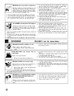
ARC  WELDING  can  be  hazardous.

ELECTRIC SHOCK can kill.

Touching  live  electrical  parts  can  cause  fatal  shocks
or  severe  burns.  The  electrode  and  work  circuit  is
electrically  live  whenever  the  output  is  on.  The  input
power  circuit  and  machine  internal  circuits  are  also
live when power  is on. In semiautomatic  or automatic
wire  welding,  the  wire,  wire  reel,  drive  roll  housing,

and  all  metal  parts  touching  the  welding  wire  are  electrically  live.
Incorrectly  installed  or  improperly  grounded  equiment  is  a  hazard.

  1.- Do  not  touch  live  electrical  parts.
  2.- W ear  dry,  hole-free  insulating  gloves  and  body  protection.
  3.- Insulate  yourself  from  work  and  ground  using  dry  insulating
mats  or  covers.

  4.- Disconnect  input  power  or  stop  engine  before  installing  or

servicing  this  equipment.

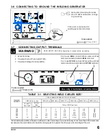
  5.- Properly  install  and  ground  this  equipment  according  to  this
            Owner's  Manual  and  national,  state,  and  local  codes.
  6.- Turn  off  all  equipment  when  not  in  use.
  7.- Do  not  use  worn,  damaged,  undersized,  or  poorly  spliced  cables.
  8.- Do  not  wrap  cables  around  your  body.
  9.- Ground  the  workpiece  to  a  good  electrical  (earth)  ground.
10.- Do  not  touch  electrode  while  in  contact  with  the  work  (ground)

circuit.

11.- Use  only  well-maintained    equipment.  Repair  or  replace  damaged

parts  at  once.

12.- Wear  a  safety  harness  to  prevent  falling  if  working  above  floor
       level.
13.- Keep  all  panels  and  cover  securely  in  place.

ARC RAYS can burn eyes and skin;
NOISE can damage hearing.

Arc  rays  from  the  welding  process  produce  intense
heat and strong ultraviolet rays  that can burn eyes and
skin. Noise from some processes can damage hearing.

1.- Wear  a  welding  helmet  fitted  with  a  proper  shade

of  filter  (see    ANSIZ49.1  listed  in  Safety  Standards)  to  protect

FUMES AND GASES can be hazardous
to your health.

Welding  produces  fumes  and  gases.  Breathing  these
fumes  and  gases  can  be  hazardous  to  your  health.

1.-  Keep  your  head  out  of  the  fumes.  Do  not  breath  the

  fumes.

2.- If inside, ventilate the area and / or use exhaust at  the arc to remove
         welding fumes  and  gases.
3.-  If  ventilation  is  poor,  use  an  approved  air-supplied  respirator.
4.-  Read  the  Material  Safety  Data  Sheets  (MSDSs)  and  the

manufacturer´s  instruction  for  metal,  consumables,  coatings,  and
cleaners.

5.- Work in a confined space only if it is well ventilated, or while wearing

an  air-supplied  respirator.  Shielding  gases  used  for  welding  can
displace air causing injury or death. Be sure the breathing air is safe.

6.-  Do  not  weld  in  locations  near  degreasing,  cleaning,  or  spraying

operations.  The  heat  and  rays  of  the  arc  can  react  with  vapors  to
form

  highly  toxic  and  irritating  gases.

7.- Do not weld on coated metals, such as galvanized, lead, or cadmium

plated  steel,  unless  the  coating  is  removed  from  the  weld  area,  the
area  is  well  ventilated,  and  if  necessary,  while  wearing  an  air-
supplied  respirator.  The  coatings  and  any  metals  containing  these
elements  can  give  off  toxic  fumes  if  welded.

FLYING SPARK AND HOT METAL can
cause injury

Chipping  and  grinding  cause  flying  metal  .  As  welds
cool,  they  can  throw  off  slag.

1.-  Wear  approved  face  shield  or  safety  goggles.  Side  shields

recommended.

2.-  Wear  proper  body  protection  to  protect  skin.

your  face  and  eyes  when  welding  or  watching.
2.- Wear  approvedsafety  glasses.  Side  shields  recommended.
3.- Use  protective  screens  or  barriers to  protect  others  from  flash  and

glade;  warn  others  not  to  watch  the  arc.

4.- Wear  protective  clothing  made  from  durable,  flame-  resistant  mate

rial  (wool  and  leather)  and  foot  protection.

5.- Use  approved  ear  plugs  or  ear  muffs  if  noise  level  is  high.

i

Содержание BRONCO 255K XD

Страница 1: ...ENERATOR PROCESS STICK SMAW DESCRIPTION CC CV TIG GTAW MIG GMAW WELDINGGENERATORTYPE AC DC CONSTANTCURRENT CONSTANTVOLTAGE CC CV PM1323 REV 0 E 21 01 2021 304 855 T M OWNER S MANUAL GIVETHISMANUALTOTH...

Страница 2: ...trol 9 4 6 Engine Control 9 4 7 Burnbank Optional 9 4 8 Mig welding outputs and settings controls 10 4 9 Optional controls and indicators 11 SECTION 5 AUXILIARY POWER 12 5 1 Receptacles 12 5 2 Wiring...

Страница 3: ...ged parts at once 12 Wear a safety harness to prevent falling if working above floor level 13 Keep all panels and cover securely in place ARC RAYS can burn eyes and skin NOISE can damage hearing Arc r...

Страница 4: ...ng or connecting unit 3 Have only qualified people remove guards or covers for maintenance and troubleshooting as necessary 4 To prevent accidental stating during servicing disconnect negative battery...

Страница 5: ...riod follow rated duty cycle Reduce current or reduce duty cycle before starting to weld again Do not block or filter airflow to unit STATIC ESD can damage PC boards Put on grounded wrist strap BEFORE...

Страница 6: ...y signal words SECTION 1 SAFETY SIGNALS AND SYMBOLS WARNING CAUTION IMPORTANT Statements identify special instructions necessary for the most efficient operation of thisequipment WARNING statements id...

Страница 7: ...PERES 240 V The ac power curve shows the auxiliary power in amperes available at the 120 and 240 volts receptacles L H IDLE 2200RPM The fuel consumption curves shows Typical Fuel use under weld or pow...

Страница 8: ...CC DC CV DC 175 300 20 90 30 40 50 60 70 80 100 10 Duty cycle is percentage of 10 minutes that unit can work at rated load without overheating This unit can work at 100 of Duty cycle Allowing a const...

Страница 9: ...1 SELECTING A LOCATION MOVING WELDING SOURCE READ SAFETY BLOCKS at beginning of manual before proceeding 1 Keep free space 457mm 18 around the unit for a good air flow 2 Lifting eye Use only for lift...

Страница 10: ...tick Check oil level after fueling with unit on level surface If oil level is not up to full mark on dipstick add oil see engine manual for more specifications 3 Oil fill tube If fuel do not close to...

Страница 11: ...0 2 0 4 2 1 1 0 2 0 3 0 3 1 1 0 2 0 3 0 4 0 2 1 0 2 0 3 0 4 0 2 2 0 1 2 0 3 0 4 0 2 2 0 2 3 0 1 0 3 0 4 0 2 2 0 2 3 0 2 3 0 1 0 3 0 4 0 2 2 0 2 3 0 2 4 0 Weld cable size AWG is based on either a 4 vol...

Страница 12: ...late total cable length in weld circuit b Determine maximum welding current and duty cycle c Use table 3 1 to select proper cable size 2 Terminal lug Use lugs of proper amperage capacity and hole size...

Страница 13: ...w range in coarse range selector CD current VC mode See sec 4 3 CAUTION ARCING can damage switch Do not change AC DC polarity switch position while welding Arcing inside switch can damage contact caus...

Страница 14: ...not Use Place the Switch in the OFF position to preven discharging the battery 4 CHOKE Choke control is provided for varying the fuel air mixture to the engine Set ignition switch in Start position P...

Страница 15: ...CIRCUIT BREAKER CB6 Protects to 24 Vac winding agains overloads on receptacle RC4 4 RECEPTACLE RMT 14 RC4 Insert the conector of the wire feeder and tighten firmly this reeceptacle supply 24 Vac to w...

Страница 16: ...uipment Install Prepare wire feeder Use The Safety Equiment Set Controls Open Gas Valve Start the Engine Turn On Auxiliary Equipment Turn On Wire Feeder Begin to Weld Install Connect the Equipment Ins...

Страница 17: ...e button to reset CB1 or CB2 6 circuit Reset CB3 AND CB4 CB3 and CB4 protect RC1 RC2 and RC3 The combined power of all receptacles is limited to 10 0kVA kW nominal generator Example If 20 A is draw fr...

Страница 18: ...rs Strip conductors enough to make good contact with plug terminals Make plug connections and reisntall outer shell and cord grip Tighten assembly screws onto shell Do not cover tighten 9 Auxiliary Po...

Страница 19: ...tighten Battery Connections Service Air Cleaner 100 HOURS Replace Fuel Filter Engine Manual Check Valve Clearance Repair Or Replace Damaged Cables Check Spark Plugs 1000 HOURS Blow out Or Vacuum Insi...

Страница 20: ...rmance at 0 F 18 C 430 Amps Engine RPM no load Weld power 3700 Idle 2200 Changeeachyear Spark plugGap 0 030 in 0 8 mm Spark plug STD Part number 1213202 S Check daily oil level Recomended oil SAE 30 C...

Страница 21: ...ely with air Impregnate the foam rubber element with SAE 30 oil and wring the oil excess 2 Filter Replace if filter is damage or dirty 6 4 OIL CHANGE OIL FILTER AND FUEL FILTER Stop engine 1 Oil drane...

Страница 22: ...If the battery voltage is less than 12 4 volts recharge the battery as instructed by the battery charger To replace the battery do the following Disconnect the battery cables negative cable first 8 Ba...

Страница 23: ...o the solenoid valve and adjust the following Slide the solenoid valve to front for increasing the speed or to back for decreasing the speed up to adjust the engine speed to 2200 rpm and tight the scr...

Страница 24: ...NING READ SAFETY BLOCKS at beginning of manual before proceeding 1 Fuse F6 The fuse F6 protect the engine electrical sistem from overload if F6 is open the battery no charge 6 8 ENGINE ELECTRIC SYSTEM...

Страница 25: ...TIC WELD OUTPUT HIGH OR LOW WELD OUTPUT Clean tighten all weld connections on welder generator Contact your authorized sevice center for clean slip rings and install new brushes if necessary TABLE 6 1...

Страница 26: ...ERATION BATTERY DISCHARGES BETWEEN USES Tune engine according to engine manual Check and adjust engine speed Check continuity of speed control switch SW7 and replace if necessary UNSTABLE OR SLUGGISH...

Страница 27: ...E MEV SPEED MODULE CT 1 CURRENT TRANSFORMER RC4 RECEPTACLE 14SKT F6 INCLUDED IN THE HARNESS AC 1 8 16 16 19 17 7 P DC Z S 1 F 3 6 4 WORK V C C2 R2 SR 1 33 A 33 A CB3 CB6 CB8 CB7 RC4 CB1 CB2 33 33 B W...

Страница 28: ...rement in watts 120 V x 4 5 A 540 W Therefor the individual load applied by the drill is 540Watts EXAMPLE 2 If a flood lamp is rated at 200W the individual load applied by the lamp is 200W if three 20...

Страница 29: ...P 1 HP 1 1 2 HP 2 HP 3 HP 5 HP 2020 3075 4500 6100 8200 10550 15900 23300 720 975 1400 1600 2200 2850 3900 6800 Capacitor Start Induction Run 1 1 2 HP 5 HP 7 1 2 HP 10 HP 8100 23300 35000 46700 2000 6...

Страница 30: ...A FIG 7 3 POWER REQUIRED TO START MOTOR FIG 7 4 STARTING AMPERAGE CALCULATION G KVA HP 6 3 H 7 1 J 8 0 K 9 0 L 10 0 M 11 2 N 12 5 P 14 0 1 MOTOR RATING LABEL 2 MOTOR START CODE Determine power requir...

Страница 31: ...35 Panel front Panel side Right Panel cover Panel side Left Gasket baffle assembly Baffle support Frame lifting Baffle lower Reactor Stabilizer Mounting support Fuel tank assembly Fuel sender Frame fr...

Страница 32: ...PM1323 FIG 9 1 GENERAL ASSEMBLIY 1 2 5 4 8 9 14 15 16 13 12 10 11 7 6 24 23 22 21 20 18 19 25 27 28 17 26 30 30 29 31 3 32 33 34 35 27...

Страница 33: ...2 3 4 5 6 7 8 9 10 engine adapter Fan aluminium Bearing secure Cover front Bearing Brushes assembly Brushes Brushes holder Brushes cover Brushes support stator Rotor Fan rotor I D ITEM PA1003 PV0240 M...

Страница 34: ...03985 MM04391 PC1508 PT1395 PP4303 PP4304 MP07978 PM0330 MP08417 MC10319 MC10192 MR02583 MR10523 Rheostat 100 w 10 Nameplate upper Panel front Switch range Switch polarity Receptacle duplex 120 Vac 20...

Страница 35: ...PM1323 6 7 21 8 17 15 16 14 18 12 1 2 3 3 3 4 5 19 20 10 9 11 16 13 30...

Страница 36: ...ate Rectifier Positive Negativeplate Rectifier support Filter consisting of Resistor 1 K Capacitor 47 F 200V Diode 6A 600 V Is included in the harness Rectifier 30 A 600 V Holder SB 500 6 Speed contro...

Страница 37: ...motor drive system drive roll excluded and any other part the requires the removal of sheet metal 2 1 Year Parts Labour CG1 Dart Track Cutter excluding tracks Welding positioners turning rollers Auto...

Страница 38: ...NOTES...

Страница 39: ...SERVICE CENTER FAX MAP CANADA LTD 325 Healey Road Unit 1 Bolton ON L7E 5C1 Canada Phone 905 951 2788 Toll Free 800 757 4445 Fax 905 951 6256...

Отзывы: