background image

Removal and Replacement Procedures 

Compaq ProLiant BL20p Server Blade Maintenance and Service Guide 

2-5


COMPAQ CONFIDENTIAL

 Codename: AvalancheX Part Number: 316080-001 Last Saved On: 12/18/02 11:31 AM 


CAUTION:

  After you press the release button, the server blade is unlocked from the 

enclosure. Use both hands to support the server blade when you remove it from the rack. 

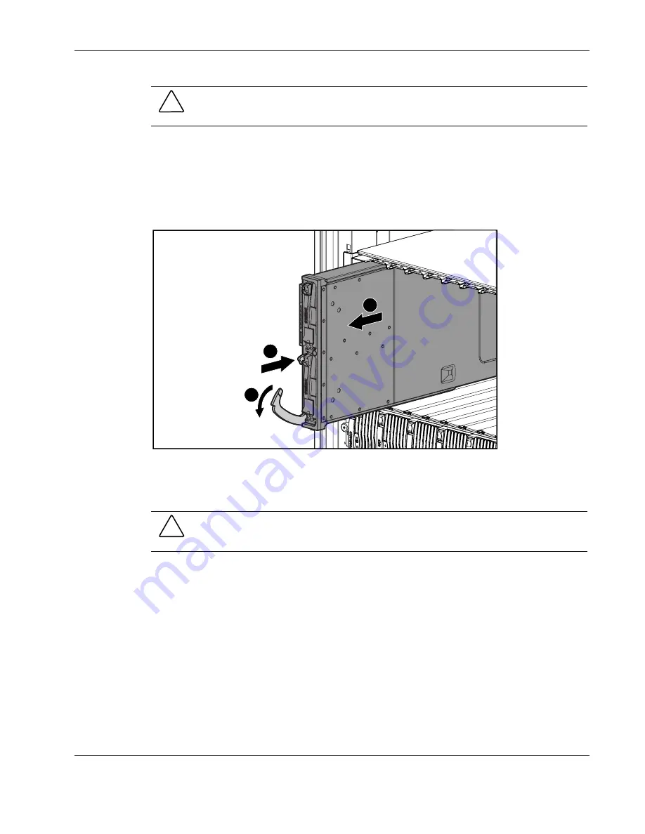
3.  Remove the server blade from the server blade enclosure: 

a.  Press the release button (1). 

b.  Open the lever (2). 

c.  Grasp the lever and slide the server blade from the enclosure (3). Place a hand under 

the server blade to support it as you remove it from the enclosure. 

1

2

3


Figure 2-2:  Removing the server blade from the server 
blade enclosure 

d.  Place the server blade on a flat, level surface. 


CAUTION:

  Always populate server blade enclosure bays with either a server blade or server 

blade blank. Operating the enclosure without a server blade or server blade blank results in 
improper airflow and improper cooling that can lead to thermal damage. 

Reverse steps 1 through 3 to install and power up a server blade. Server blades are set to 
power up automatically upon insertion. If you have changed this setting, use the Power 
On/Standby button or iLO Virtual Power Button feature to power up the server blade. 

For more information about iLO, refer to the 

Compaq Integrated Lights-Out User Guide

Содержание BL20p - ProLiant - G2

Страница 1: ...vice Guide Part Number 316080 001 January 2003 First Edition This document provides detailed instructions for maintenance and service personnel It includes removal and replacement procedures spare parts information an overview of diagnostic tools locations for interface components and related specifications for the Compaq ProLiant BL20p server blade ...

Страница 2: ...ries Compaq shall not be liable for technical or editorial errors or omissions contained herein The information in this document is provided as is without warranty of any kind and is subject to change without notice The warranties for Compaq products are set forth in the express limited warranty statements accompanying such products Nothing herein should be construed as constituting an additional ...

Страница 3: ...Exploded View 1 2 Server Blade Spare Parts List 1 3 Chapter 2 Removal and Replacement Procedures Safety Considerations 2 1 Electrostatic Discharge Information 2 1 Server Blade Warnings and Cautions 2 1 Rack Warnings and Cautions 2 2 Symbols on Equipment 2 3 Server Blade Components 2 4 Server Blade Preparation 2 4 Access Panel 2 6 Hard Drive Blanks 2 7 Hot Plug SCSI Hard Drives 2 8 DIMMs 2 9 Proces...

Страница 4: ...Pressing the Power On Standby button 2 4 2 2 Removing the server blade from the server blade enclosure 2 5 2 3 Removing the server blade access panel 2 6 2 4 Removing a hard drive blank 2 7 2 5 Removing a hot plug SCSI hard drive 2 8 2 6 Removing a DIMM 2 9 2 7 Removing a PPM 2 10 2 8 Removing a processor assembly 2 11 2 9 Removing the Battery Backed Write Cache Enabler 2 12 2 10 Removing a blower...

Страница 5: ...4 7 Power On Standby button 4 9 4 8 Server blade system switches 4 10 List of Tables 1 1 Server Blade Spare Parts List 1 3 3 1 Diagnostic Tools 3 2 4 1 ProLiant BL20p Server Blade Rear Panel Connectors 4 3 4 2 System Board Components and Connectors 4 4 4 3 Diagnostic Cable Connectors 4 5 4 4 ProLiant BL20p Server Blade Front Panel LEDs 4 6 4 5 Hot Plug SCSI Hard Drive LEDs 4 7 4 6 Server Blade Sys...

Страница 6: ...rning could result in bodily harm or loss of life CAUTION Text set off in this manner indicates that failure to follow directions could result in damage to equipment or loss of information IMPORTANT Text set off in this manner presents clarifying information or specific instructions NOTE Text set off in this manner presents commentary sidelights or interesting points of information Important Safet...

Страница 7: ...TION To properly ventilate the system you must provide at least 7 6 cm 3 0 in of clearance at the front and back of the server CAUTION The computer is designed to be electrically grounded earthed To ensure proper operation plug the AC power cord into a properly grounded AC outlet only NOTE Any indications of component replacement or printed wiring board modifications may void any warranty Where to...

Страница 8: ...ller In the United States call 1 800 345 1518 In Canada call 1 800 263 5868 For Compaq technical support In the United States and Canada call 1 800 OK COMPAQ For Compaq technical support phone numbers outside the United States and Canada visit the Compaq website www compaq com Text Conventions This document uses the following conventions Italic type is used for complete titles of published guides ...

Страница 9: ...Codename AvalancheX Part Number 316080 001 Last Saved On 12 18 02 11 28 AM 1 Illustrated Parts Catalog This chapter provides illustrated parts and spare parts lists for the Compaq ProLiant BL20p server blade components Refer to Tables 1 1 through 1 6 for the names of referenced spare parts ...

Страница 10: ... Blade Maintenance and Service Guide COMPAQ CONFIDENTIAL Codename AvalancheX Part Number 316080 001 Last Saved On 12 18 02 11 28 AM ProLiant BL20p Server Blade Components Server Blade Exploded View 4 3 11 10 1 2 7 5 6 9 8 Figure 1 1 Server blade exploded view ...

Страница 11: ...OL 237555 001 7 Compaq Smart Array 5i Controller module 237550 001 System Components 8 Intel Pentium III processor assembly 1 4 GHz 237504 001 9 Processor power module PPM 237553 001 10 Power converter module 190 W 237554 001 11 Blower assembly 237569 001 Miscellaneous 12 Plastics and hardware kit 237583 001 Bezel assembly Anchor pins 4 EMI fastener clips Ejector latch System board thumbscrew 13 R...

Страница 12: ...CONFIDENTIAL Codename AvalancheX Part Number 316080 001 Last Saved On 12 18 02 11 28 AM Table 1 1 Server Blade Spare Parts List continued Item Description Spare Part Number Options 20 Dual NC7780 Gigabit NIC upgrade module 237585 001 21 Battery Backed Write Cache Enabler with cable 260740 001 Not shown ...

Страница 13: ...r microcircuitry Proper packaging and grounding techniques are necessary precautions to prevent damage To prevent electrostatic damage observe the following precautions Transport products in static safe containers such as conductive tubes bags or boxes Keep electrostatic sensitive parts in their containers until they arrive at static free stations Cover workstations with approved static dissipatin...

Страница 14: ...d server blades from their enclosures before installing or removing the enclosures Use caution and get help to lift and stabilize enclosures during installation or removal especially when the enclosure is not fastened to the rack WARNING Always use at least two people to lift a power supply enclosure or server blade enclosure into the rack If the enclosure is being loaded into the rack above chest...

Страница 15: ...eeps the system in operation during a power failure CAUTION Always ensure that equipment is properly grounded before beginning any installation procedure Electrostatic discharge resulting from improper grounding can damage electronic components For more information refer to the setup and installation guide Symbols on Equipment 25 kg 55 lb Any product or assembly marked with these symbols indicates...

Страница 16: ... does not completely shut off with the front panel Power On Standby switch or Integrated Lights Out iLO Virtual Power Button feature The function toggles between on and standby modes rather than on and off The standby position removes power from most electronics and the drives but portions of the power supply and some internal circuitry remain active To service internal server blade components 1 I...

Страница 17: ...lade to support it as you remove it from the enclosure 1 2 3 Figure 2 2 Removing the server blade from the server blade enclosure d Place the server blade on a flat level surface CAUTION Always populate server blade enclosure bays with either a server blade or server blade blank Operating the enclosure without a server blade or server blade blank results in improper airflow and improper cooling th...

Страница 18: ...access panel 1 Power down the server blade and remove it from the server blade enclosure Refer to the Server Blade Preparation section in this chapter 2 Loosen the thumbscrew 1 3 Press down on the thumb indentations slide the access panel toward the rear of the unit about 1 25 cm 0 5 in and lift to remove the panel 2 1 2 2 Figure 2 3 Removing the server blade access panel Reverse steps 1 through 3...

Страница 19: ...ease buttons simultaneously 1 2 Pull the blank out of the drive bay 2 1 2 1 Figure 2 4 Removing a hard drive blank CAUTION Always populate hard drive bays with either a hot plug SCSI hard drive or hard drive blank Operating the server blade without a hot plug SCSI hard drive or hard drive blank results in improper airflow and improper cooling that can lead to thermal damage To replace the hard dri...

Страница 20: ... drive IMPORTANT It is not necessary to power down the server blade before removing or replacing a hot plug SCSI hard drive To remove a hot plug SCSI hard drive 1 Press the release button 1 2 Open the ejector lever 2 3 Slide the drive out of the drive cage 3 1 2 3 Figure 2 5 Removing a hot plug SCSI hard drive CAUTION Always populate hard drive bays with either a hot plug SCSI hard drive or hard d...

Страница 21: ... the access panel Refer to the Access Panel section in this chapter NOTE The server blade ships with at least two DIMMs installed in slots 1A and 2A 3 Open the DIMM slot latches 1 4 Remove the DIMM from the slot 2 1 2 1 Figure 2 6 Removing a DIMM CAUTION For proper DIMM configuration refer to the setup and installation guide CAUTION Use only Compaq DIMMs DIMMs from other sources may adversely affe...

Страница 22: ...ssor Power Module To remove a PPM 1 Power down the server blade and remove it from the server blade enclosure Refer to the Server Blade Preparation section in this chapter 2 Remove the access panel Refer to the Access Panel section in this chapter 3 Open the latches on the sides of the PPM slot 1 4 Remove the PPM from the slot 2 1 1 2 Figure 2 7 Removing a PPM Reverse steps 1 through 4 to replace ...

Страница 23: ...Access Panel section in this chapter CAUTION Always disengage the heatsink clip before raising the processor ejector lever to avoid damaging the pins 3 Disengage the retaining clip 1 Be sure that the clip unfastens from both sides of the processor socket 4 Lift the ejecting lever 2 5 Remove the processor assembly 3 1 2 3 Figure 2 8 Removing a processor assembly CAUTION Do not disassemble the proce...

Страница 24: ...fer to the Server Blade Preparation section in this chapter 2 Remove the access panel Refer to the Access Panel section in this chapter 3 Disconnect the Battery Backed Write Cache Enabler cable from the Battery Backed Write Cache Enabler 1 4 Disconnect the Battery Backed Write Cache Enabler cable from the Smart Array 5i Controller module 2 5 Lift the Battery Backed Write Cache Enabler to unseat it...

Страница 25: ...move the blower assembly 1 Power down the server blade and remove it from the server blade enclosure Refer to the Server Blade Preparation section in this chapter 2 Remove the access panel Refer to the Access Panel section in this chapter 3 Press the blower retention tabs 1 4 Rotate the blower assembly up and lift it 2 2 1 1 Figure 2 10 Removing a blower assembly Reverse steps 1 through 4 to repla...

Страница 26: ... to the Server Blade Preparation section in this chapter 2 Remove the access panel Refer to the Access Panel section in this chapter 3 Remove the blower assembly Refer to the Blower Assembly section in this chapter 4 Disconnect the Battery Backed Write Cache Enabler cable if the option is installed 1 5 Turn the anchor pins one quarter turn counterclockwise 2 6 Grasp the front and back of the modul...

Страница 27: ...Refer to the Server Blade Preparation section in this chapter 2 Remove the access panel Refer to the Access Panel section in this chapter 3 Remove the Battery Backed Write Cache Enabler if the option is installed Refer to the Battery Backed Write Cache Enabler section in this chapter 4 Turn the anchor pins one quarter turn counterclockwise 1 5 Press the retaining tab outward from the module 2 6 Gr...

Страница 28: ...ter 3 Remove any hot plug SCSI hard drives or hard drive blanks If any hard drive blanks are installed refer to the Hard Drive Blanks section in this chapter If any hot plug SCSI hard drives are installed refer to the Hot Plug SCSI Hard Drives section in this chapter 4 Remove the blower assembly Refer to the Blower Assembly section in this chapter 5 Grasp the SCSI backplane above the system board ...

Страница 29: ... blanks are installed refer to the Hard Drive Blanks section in this chapter If any hot plug SCSI hard drives are installed refer to the Hot Plug SCSI Hard Drives section in this chapter 4 Remove the blower assembly Refer to the Blower Assembly section in this chapter 5 Remove the SCSI backplane Refer to the SCSI Backplane section in this chapter 6 Remove the two retaining screws from the bottom o...

Страница 30: ...ese dioxide or a vanadium pentoxide battery There is risk of fire and burns if the battery pack is not handled properly To reduce the risk of personal injury Do not attempt to recharge the battery Do not expose to temperatures higher than 60 C Do not disassemble crush puncture short external contacts or dispose of in fire or water Replace only with the spare designated for this product CAUTION Los...

Страница 31: ...t BL p Class System Setup and Installation Guide for more information To remove the system board battery 1 Power down the server blade and remove it from the server blade enclosure Refer to the Server Blade Preparation section in this chapter 2 Remove the access panel Refer to the Access Panel section in this chapter 3 Locate the battery holder on the system board Figure 2 16 Battery holder 4 Open...

Страница 32: ...L20p Server Blade Maintenance and Service Guide COMPAQ CONFIDENTIAL Codename AvalancheX Part Number 316080 001 Last Saved On 12 18 02 11 31 AM 5 Remove the battery Figure 2 18 Removing the battery Reverse steps 1 through 5 to replace the system board battery ...

Страница 33: ...this chapter 5 Remove the processor assemblies Refer to the Processor Assembly section in this chapter 6 Remove the Battery Backed Write Cache Enabler if the option is installed Refer to the Battery Backed Write Cache Enabler section in this chapter 7 Remove the blower assembly Refer to the Blower Assembly section in this chapter 8 Remove the Compaq Smart Array 5i Controller module Refer to the Co...

Страница 34: ...s 14 Slide the system board toward the front of the server blade Be sure that the board unseats from the power converter module and all the alignment keys 15 Lift the system board until it comes off the alignment keys Figure 2 21 Disengaging the system board 16 Lift the edge of the system board nearest the DIMM slots 1 The edge of the system board nearest the Smart Array 5i Controller module conne...

Страница 35: ...ber 316080 001 Last Saved On 12 18 02 11 31 AM 1 1 2 Figure 2 22 Removing the system board Reverse steps 1 through 17 to replace the system board Server Blade Blanks To remove a server blade blank 1 Press the release buttons simultaneously 1 2 Slide the server blade blank from the server blade enclosure 2 1 1 2 Figure 2 23 Removing a server blade blank ...

Страница 36: ...12 18 02 11 31 AM CAUTION Always populate server blade enclosure bays with either a server blade or server blade blank Operating the enclosure without a server blade or server blade blank results in improper airflow and improper cooling that can lead to thermal damage To replace a server blade blank align the blank with the empty bay and slide it in until the blank is fully seated ...

Страница 37: ...uide 3 1 COMPAQ CONFIDENTIAL Codename AvalancheX Part Number 316080 001 Last Saved On 12 18 02 11 34 AM 3 Diagnostic Tools This chapter is an overview of software and firmware diagnostic tools that are available for configuring monitoring and managing the system ...

Страница 38: ...recovery Unattended Recovery logs the error information to the IML resets the server blade and tries to restart the operating system Run RBSU and set ASR 2 to enable this tool Compaq Diagnostics Compaq Diagnostics tests and verifies operation of Compaq hardware If Compaq Diagnostics finds a hardware failure it isolates the replaceable part if possible Access Compaq Diagnostics when POST detects a ...

Страница 39: ...IML utilities The IML requires Compaq operating system management drivers Refer to the ProLiant Essentials Rapid Deployment Pack CD for instructions on installing the appropriate drivers Option ROM Configuration for Arrays ORCA The Option ROM Configuration for Arrays Utility is a menu driven utility that does not require a CD and can be started when the server blade is booting This utility enables...

Страница 40: ...uide COMPAQ CONFIDENTIAL Codename AvalancheX Part Number 316080 001 Last Saved On 12 18 02 11 34 AM Firmware Upgrades for Management Modules For information about upgrading server blade management module or power management module firmware refer to the Compaq website www compaq com ...

Страница 41: ...Service Guide 4 1 COMPAQ CONFIDENTIAL Codename AvalancheX Part Number 316080 001 Last Saved On 12 18 02 11 38 AM 4 Connectors LEDs and Switches This chapter explains the location and function of system connectors internal and external LEDs and switches ...

Страница 42: ...em components ProLiant BL20p server blades Server blade enclosures and server blade management modules Power enclosures and power management modules RJ 45 patch panels Interconnect switches Bus bars and power bus boxes Diagnostic cable and diagnostic station ProLiant BL20p Server Blade Front Panel Connectors The server blade has one front panel connector a diagnostic port that accepts the diagnost...

Страница 43: ... Use the following figure and table to identify ProLiant BL20p server blade rear panel connectors 1 2 Figure 4 2 ProLiant BL20p server blade rear panel connectors Table 4 1 ProLiant BL20p Server Blade Rear Panel Connectors Item Description 1 Power connector 2 Signal connector System Board Components and Connectors Use the following figure and table to identify ProLiant BL20p system board component...

Страница 44: ...ard components and connectors Table 4 2 System Board Components and Connectors Item Description 1 NIC module 2 NIC module connectors 3 Smart Array 5i Controller module 4 Smart Array 5i connectors 5 Blower assembly connectors 6 Battery 7 Processor power module PPM slot 2 8 Processor socket 2 9 Processor socket 1 populated 10 PPM slot 1 populated 11 DIMM slots 1A through 4B Diagnostic Cable Use the ...

Страница 45: ... 12 18 02 11 38 AM 1 2 3 Figure 4 4 Diagnostic cable connectors Table 4 3 Diagnostic Cable Connectors Item Description 1 Server blade connector 2 iLO RJ 45 10 100 Ethernet connector 3 Kernel debug connector LEDs Use the following section to identify LEDs on the following ProLiant BL p Class system components ProLiant BL20p server blade front panel Hot plug SCSI hard drives ...

Страница 46: ... LED locations and functions UID NIC 1 NIC 2 NIC 3 1 2 3 4 5 6 Figure 4 5 ProLiant BL20p server blade front panel LEDs Table 4 4 ProLiant BL20p Server Blade Front Panel LEDs Item LED Description Status 1 Unit identification Blue Flagged Blue flashing Management mode Off No remote management 2 Health Green Normal status Flashing Booting Amber Degraded status Red Critical status 3 NIC 1 4 NIC 2 5 NI...

Страница 47: ...rray Use the following figure and table to identify LED locations and functions 1 2 3 Figure 4 6 Hot plug SCSI hard drive LEDs Table 4 5 Hot Plug SCSI Hard Drive LEDs 1 Activity 2 Online 3 Fault Means On Off Off Do not remove the drive Removing a drive during this process causes data loss The drive is being accessed and is not configured as part of an array On Flashing Off Do not remove the drive ...

Страница 48: ...wered on controller is not accessing the drive Or The drive is configured as an online spare Off Off On OK to replace the drive online The drive has failed and has been placed off line Off On Off OK to replace the drive online if a predictive failure alert is received refer to the following section for details provided that the array is configured for fault tolerance and all other drives in the ar...

Страница 49: ...unctions of push button and system switches Buttons Use the following section to identify push button switches on the system hardware Power On Standby Button Setting the server blade Power On Standby button to the standby position removes power from most areas of the server blade This process may take 30 seconds during which time some internal circuitry remains active Use the following figure to i...

Страница 50: ...able you to change certain settings or to perform advanced diagnostic procedures The following sections explain the functions of each switch Use the following figure and table to identify switch locations and functions 1 2 3 4 Figure 4 8 Server blade system switches Table 4 6 Server Blade System Switches Item Description 1 iLO switch SW2 2 System switch SW3 3 System configuration switch SW1 4 Non ...

Страница 51: ...eserved 2 iLO security override Off iLO security is enabled iLO access requires a valid user ID and password Also the iLO boot block access is disabled and the iLO boot block cannot be flashed On iLO security is disabled iLO access is possible without a valid user ID or password Also the iLO boot block access is enabled and the iLO boot block can be flashed 3 Reserved 4 Reserved System Switch SW3 ...

Страница 52: ...p analysis is an essential part of eliminating reliability problems such as hangs or crashes in operating systems device drivers and applications Crashes can freeze a system requiring you to do a hard reset Resetting the system erases any information that supports root cause analysis Systems running Microsoft Windows 2000 experience a blue screen trap when the operating system crashes When this ha...

Страница 53: ...ocedures 4 Change position 4 of SW1 to on 5 Install the access panel Refer to the Access Panel section in Chapter 2 Removal and Replacement Procedures 6 Connect the server blade to system power Install the server blade in the enclosure Connect the server blade to the diagnostic station 7 Power up the server blade Press the Power On Standby button on the front of the server blade Use the virtual po...

Страница 54: ...Remove the access panel Refer to the Access Panel section in Chapter 2 Removal and Replacement Procedures 4 Change positions 1 and 4 of SW1 to on 5 Install the access panel Refer to the Access Panel section in Chapter 2 Removal and Replacement Procedures 6 Connect the server blade to system power Install the server blade in the enclosure Connect the server blade to the diagnostic station 7 Power u...

Страница 55: ...TIAL Codename AvalancheX Part Number 316080 001 Last Saved On 12 18 02 11 40 AM 5 Specifications This chapter provides operating and performance specifications for the following Compaq ProLiant BL p Class system components ProLiant BL20p server blade Memory Wide Ultra3 SCSI hard drives ...

Страница 56: ...rating 10 to 90 Non operating Shipping Storage 10 to 90 10 to 95 Maximum wet bulb temperature 28 C 82 F 1 Operating temperature has an altitude derating of 1 C per 304 8 m 1 8 F per 1 000 ft No direct sunlight Upper operating limit is 3 048 m 10 000 ft or 70 Kpa 10 1 psia Upper non operating limit is 9 144 m 30 000 ft or 30 3 KPa 4 4 psia 2 Storage maximum humidity of 95 is based on a maximum temp...

Страница 57: ...36 419 6 MB 72 839 2 MB Height One third 1 0 in One third 1 0 in One third 1 0 in One third 1 0 in Size 3 5 in 3 5 in 3 5 in 3 5 in Interface Wide Ultra3 Wide Ultra3 Wide Ultra3 Wide Ultra3 Transfer rate 160 MB sec 160 MB sec 160 MB sec 160 MB sec Rotational speed 10 000 RPM 10 000 RPM 10 000 RPM 10 000 RPM Bytes per sector 512 512 512 512 Logical blocks 17 773 524 35 566 080 71 132 000 142 264 00...

Страница 58: ...ings cautions 2 18 BIOS settings reconfiguring 2 18 blower assembly removing 2 13 replacing 2 13 spare part numbers 1 3 blower assembly connectors 4 4 buttons Power On Standby 2 4 4 9 C cables Battery Backed Write Cache Enabler 2 12 2 14 diagnostic 4 5 power button LED board 2 16 clearing the system configuration 4 13 Compaq authorized reseller ix Compaq Diagnostics utility access 3 2 description ...

Страница 59: ... removing 2 8 replacing 2 8 specifications 5 3 humidity ranges See specifications I icons symbols on equipment 2 3 iLO RBSU See Integrated Lights Out ROM Based Setup Utility iLO RBSU IML See Integrated Management Log IML Insight Manager See Compaq Insight Manager 7 installing See replacing Integrated Lights Out iLO system board switch 4 10 4 11 Integrated Lights Out ROM Based Setup Utility iLO RBS...

Страница 60: ... plug SCSI hard drives 2 8 NIC module 2 15 power button LED board 2 17 PPM 2 10 processor assembly 2 11 SCSI backplane 2 16 server blade blank 2 23 server blades 2 5 Smart Array 5i Controller module 2 14 system board server blade 2 21 replacing access panel 2 6 battery 2 20 Battery Backed Write Cache Enabler 2 12 blower assembly 2 13 DIMMs 2 9 hard drive blank 2 7 hot plug SCSI hard drives 2 8 NIC...

Страница 61: ...board thumbscrew spare part number 1 3 system board server blade removing 2 21 replacing 2 23 spare part number 1 3 system configuration switch 4 10 4 12 T technician notes vii telephone numbers ix temperature ranges See specifications text conventions ix thumb indentations 2 6 U unit identification UID LEDs 4 6 utilities Compaq Diagnostics 3 2 Compaq Insight Manager 7 3 2 Compaq Survey Utility 3 ...

Отзывы: