www.commscope.com
860543388
Instruction Sheet
Page 15 of 19
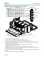
SYSTIMAX 360 1U/2U/4U Modular Shelf MPO Upgrade Kit Installation
1. From the front of the rack, remove front door by gently pressing both upper corners to release the
latches. Then lift the door off the trough.
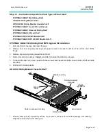
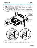
2. Remove the adhesive tape from backplane kit bottom and slide two bar mounting clips onto the
backplane kit as shown in Detail
A
.
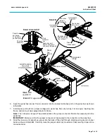
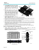
3. Insert the panel bus jumper 10-pin connector into the nearest cable bus port on the panel bus as
shown. Install spare port built into jumper cordage into panel bus frame by turning it at an angle,
inserting into frame, and turning it back perpendicular to frame. The connector is keyed. The
polarized tab on the jumper connector fits into the nearest port in the panel bus.
4. Excess panel bus jumper is coiled and secured with cable ties to cable management bar.
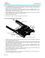
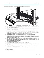
5. Facing equipment from rear of rack, prepare to install
iPatch
MPO upgrade kit by feeding ribbon cable
through faceplate slot located between two MPO bezels, gently pulling the black ribbon cable through
the opening to prevent it from kinking.
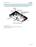
6. Slide MPO upgrade kit over bezel. Leave about 3 inches (76mm) of slack ribbon cable inside the
panel. Securely mount upgrade kit onto bezel’s latches by pushing on center and each side of the
upgrade kit until it snaps in place as shown.
7. Route ribbon cables to backplane kit.
Note:
See
Step 3b
for cable routing description, tables and drawings.
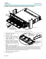
8. Attach the panel bus jumper to the top connector on the backplane kit, making sure the connector is
fully seated.
9. From the rear of the rack, mount backplane kits (one kit per row) by snapping kit onto rear cable
management bar at the rear right corner as shown.
Note:
Mount with round hole in the backplane kit facing toward the front of the shelf.
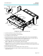
10. Replace front door.
860543388-014
Detail A


