TECP-90-814 • Rev C • October 2020
Page 6
© 2020
CommScope
. All Rights Reserved.
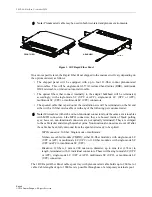
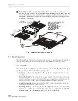
Figure 3. RapidReel Cable Spool Tray and Panel
1.2
Basic Components
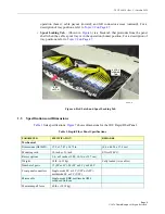
The 1RU Rapid Fiber Panel has two high-level components: the panel shell and the RapidReel
cable spool tray. These components are described in more detail in the following topics.
1.2.1
Panel Shell
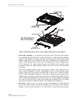
The panel shell, shown in
, provides a mounting point for the RapidReel cable spool
tray. The panel shell consists of the following components:
• Enclosure
– Houses the RapidReel cable spool tray and protects the microcable
assemblies.
•
Removable Front Cover
– Protects the equipment patch cords at the point where they
enter the panel and connect to the adapter bulkhead. A designation card attached to the
inside of the cover provides a means for identifying and recording connections.
•
Ground Connection
– Provides a point for securing a two-hole lug (used for connecting a
grounding cable) to the side of the enclosure.
•
Mounting Brackets
– Secure the panel to the equipment rack. Two sets of mounting
brackets are provided, one set for 19-inch racks and one set for 23-inch racks. The
mounting brackets may be installed to provide a 2-, 4-, or 5-inch recess.
Note:
When mounting multiple Rapid Fiber Panels into a rack or cabinet, be sure to
calculate the total weight of all the equipment being mounted to verify that it does not
exceed the rack or cabinet manufacturer’s maximum weight allowance. In Zone 4
Earthquake applications, exceeding the weight rating can compromise the integrity of the
rack during an earthquake.
NOTE: IF THE MICROCABLE ROUTES
FROM THE FRONT, INSERT
THE CABLE SPOOL
TRAY FROM THE FRONT.
IF THE MICROCABLE ROUTES
FROM THE REAR, INSERT
THE CABLE SPOOL TRAY
FROM THE REAR.
26139-A
REAR SIDE
INSTALLATION
FRONT SIDE
INSTALLATION
15 INCHES
(38.1 CM)
15 INCHES
(38.1 CM)
PANEL SHELL
RapidReel
CABLE
SPOOL
TRAY


