5
.
System Operation
PowerShift - User
Manual
Version B DRAFT2.docx
Version B
Page 13
5.5.
Operating Faults & Alarms
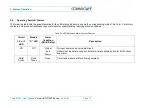
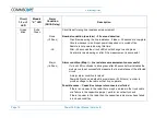
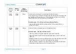
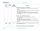
The following table lists the possible states for the LED status indicators, shows the corresponding state of the Form C alarm dry
contacts, and provides troubleshooting comments for understanding resolving alarm conditions.
Table 5-1 LED States and Alarm Contact Closures
Circuit
1, 2 or 3
LED
Module
“X” LED
Alarm
Condition
(GUI & Relay)
Description
Off
Off
Critical
and
Major
No input power on any module/circuit
GUI will not be able to connect, but alarm relays will be active for both critical
and major
Solid
Green
Solid
Green
None
Circuit and module are functioning normally
Содержание PowerShift V1
Страница 1: ...User Manual PowerShift V1 Document 7761739 Version B ...
Страница 4: ...1 General Page 4 PowerShift User Manual Version B ...
Страница 25: ......

