background image

1-Port 5Gb PoE Extender Manual

16

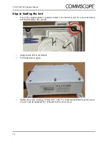
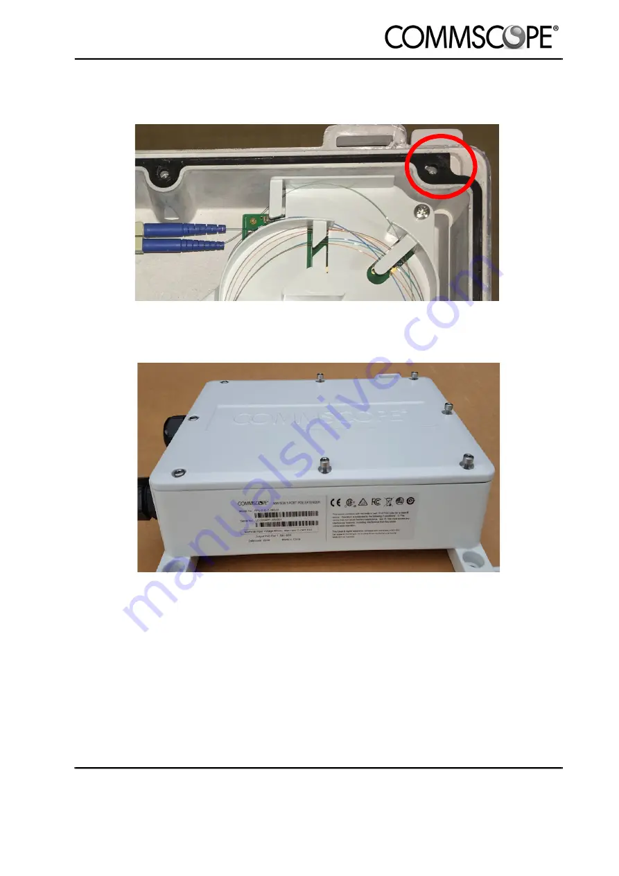
Step 6: Sealing the Unit

1.

Ensure the supplied gasket is properly seated in its channel (it only fits in one orientation) 

and that all cables are secured.

2.

Apply Loctite 222 to all lid bolts.

3.

Put the lid back in place.

.

4.

Tighten the screws to torque 2.5Nm (22.1 in-lb). It is recommended that the center screws 

on each side be tightened first, followed by the corner screws.

Содержание PFU-P-E-O-060-01

Страница 1: ...860659348 Rev A 1 Port 5Gb PoE Extender Manual 860659348 Rev A October 2020 ...

Страница 2: ......

Страница 3: ...er PFU P E O 060 01 7 4 Installation 9 Step 1 Remove Solar Shield 9 Step 3 Remove the Enclosure Lid 11 Step 4 Powered Fiber Cable Installation 11 Step 4A Splitting the Cable 11 Step 4B Installing the Cable Gland 12 Step 4C Connecting the Power Strands 13 Step 4D Connecting the fiber 13 Step 6 Sealing the Unit 16 Step 7 Mounting the Unit 17 Wall Mount 17 Pole Mount 18 Step 8 Grounding 19 Step 9 Ins...

Страница 4: ...1 Port 5Gb PoE Extender Manual This product is copyright 2020 CommScope LLC All Rights Reserved ...

Страница 5: ...quipment installation manual all data and control ports are connected to ES1 SELV NEC Class 2 conformant circuits inside the enclosure To maintain all the ports on the equipment at SELV NEC Class 2 it is essential that if any connection is made to any of these ports by other equipment the other equipment must maintain its relevant port at ES1 SELV NEC Class 2 General 1 Unless otherwise stated in t...

Страница 6: ...1 Port 5Gb PoE Extender Manual 2 ...

Страница 7: ...he instruction manual may cause harmful interference to radio communications Operation of this equipment in a residential area is likely to cause harmful interference in which case the user will be required to correct the interference at his own expense Modifications not expressly approved by the manufacturer could void the user s authority to operate the equipment under FCC rules This Class A dig...

Страница 8: ...1 Port 5Gb PoE Extender Manual 4 ...

Страница 9: ...cuit protection electronics 4 Optical to electrical Media Conversion When coupled with any standard NEC Class 2 48V DC power supply CommScope s Powered Fiber Cable system can power and communicate with PoE standard devices at far greater distances than category style copper cabling systems typically limited to 90 meters while still meeting NEC Class 2 and SELV standards eliminating the need for qu...

Страница 10: ...ts both differential and common mode Secondary Protection MOV and Inductors reduce surge voltage down to 100 150 Tertiary Protection Transient voltage suppressors work at relatively low slow surges adds an extra layer of protection against voltage spikes Protects differential mode only Clamps voltage spikes to 80 100V Additional protection elements include Cross polarity protection to simplify ins...

Страница 11: ...on of the hybrid cable component parts 12 AWG or 2mm diameter wire stripper for 12 AWG cable 16 AWG or 1 2mm wire diameter stripper for the 16 AWG cable Fastenings for wall or pole mounting Fiber splice kit and LC connectors or fiber patch cords CommScope 760243403 QWIK FUSE Installer Termination Toolkit recommended Outdoor rated Cat6 or 6a shielded copper patch cord CommScope CO11152 01 PCOSP 6S ...

Страница 12: ...1 Port 5Gb PoE Extender Manual 8 ...

Страница 13: ...e solar shield to the PoE Extender with a 3mm Allen key Slide the solar shield off the retaining lugs and put to one side Step 2 Remove the Cable Glands Unscrew the caps and then remove the plugs and grommets from the pass through connectors Note1 Do not unscrew the pass throughs from metal body of the extender These have been factory fitted and sealed to the correct torque setting ...

Страница 14: ...1 Port 5Gb PoE Extender Manual 10 ...

Страница 15: ... to a fiber terminal which is then inserted into the SFP The Powered Fiber Cable is designed to be prepared for use with only a knife a typical pair of wire strippers and optionally a wire cutter or snip To split the cable successfully follow this process As detailed below only use the knife to separate the parts for the first 20mm or so It is important that subsequent stripping is performed by si...

Страница 16: ...e supplied grommet the grommet should be positioned approximately 5cm from where the cable component parts are split out Putting a small amount of silicon grease on the cable segments will make the gland easier to install and provide added protection against water ingress 3 Thread the end of the powered fiber cable through the gland fitting on the enclosure with the fiber segment above the two cop...

Страница 17: ...d of the remaining sheath will rest in the fiber tray Place the strippers at the desired strip location close the wire strippers fully once then open Now by hand you may pull the center element jacket off revealing the aramid and optical fibers 3 Remove excess aramid as desired for termination 4 The fibers should wrap around the splice tray several times to allow for future re splicing 5 If used t...

Страница 18: ...e seal cap and grommet on to the cable as shown below Note If using a pre terminated Ethernet cable it may be necessary to remove the boot 2 With the latch facing up insert the RJ45 plug through the the cable gland fitting and into the jack After fully inserting the plug verify that the plug latch is engaged in the jack by gently pulling back on the cable ...

Страница 19: ...rque wrench tighten the screw cap onto the gland fitting Tighten to 4 N m 35in lbf ATTENTION TO PREVENT MOISTURE AND DUST FROM ENTERING THE UNIT ALL UNUSED PORTS SHOULD HAVE PLUGS INSTALLED AT ALL TIMES FAILURE TO DO SO COULD RESULT IN UNIT FAILURE ...

Страница 20: ...seated in its channel it only fits in one orientation and that all cables are secured 2 Apply Loctite 222 to all lid bolts 3 Put the lid back in place 4 Tighten the screws to torque 2 5Nm 22 1 in lb It is recommended that the center screws on each side be tightened first followed by the corner screws ...

Страница 21: ...l 17 Step 7 Mounting the Unit When vertically mounted the extender must be installed with the cable ports facing downward Wall Mount The PoE extender has 4 holes on the exterior of the device for attaching to a wall or flat surface ...

Страница 22: ...rt 5Gb PoE Extender Manual 18 Pole Mount The four slots in the raised sections on the bottom of the device may be used for pole attachment using band clamps jubilee clips PoE pole mounted with solar shield ...

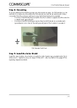
Страница 23: ... 16AWG bonding connection from the Customer s equipment earth terminal to a reliable earth ground point 2 A minimum 16AWG bonding connection from the PoE Extender to a reliable earth ground point at or close to the earth ground point of the Customer s equipment PoE Extender Earth Point Step 9 Install the Solar Shield Install the solar shield as shown below using the four Allen head screws provided...

Страница 24: ...1 Port 5Gb PoE Extender Manual 20 ...

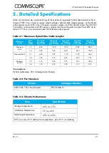
Страница 25: ...rground Ducted Table 4 1 Maximum Hybrid Fiber Cable Lengths PSU Output Voltage Cable Gauge AWG Max Cable Length m Pout 60W Max Cable Length m Pout 45 4W Max Cable Length m Pout 30 8W Max Cable Length m Pout 30W Max Cable Length m Pout 15 4W Maximum 57V 12 650 1120 1570 1595 2630 16 255 445 620 630 1040 Nominal 48V 12 460 795 1100 1120 1840 16 180 315 435 440 725 Minimum 40 5V 12 330 555 770 780 12...

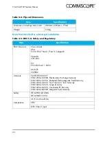
Страница 26: ...mits USA FCC CFR 47 Part 2 Part 15 Subpart B Canada ICES 003 EU EN 55032 A11 2020 AS NZS CISPR32 Immunity Per EN55035 2017 EN61000 4 2 2008 Electrostatic Discharge Immunity EN61000 4 3 2010 Radiated Electromagnetic Field Immunity EN61000 4 4 2012 Fast Transient Burst Immunity EN61000 4 5 2014 Surge Immunity EN61000 4 6 2013 Conducted RF Immunity EN61000 4 8 2009 Magnetic Field Immunity Safety IEC ...

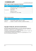
Страница 27: ...ign equivalents For patents see www commscope com ProductPatent ProductPatent aspx For technical assistance customer service or to report any missing damaged parts visit us at http www commscope com SupportCenter Environmental ETSI EN 300 019 1 4 V2 3 1 2013 08 Class 4 1E EN 60068 2 52 1996 REACH SVHC RoHS2 2011 65 EU EN 60529 1992 A2 2013 IP68 Table 4 6 Communications Item Specification Optical P...

Отзывы: