LS-37L
3.5 inch Desktop Miniboard
User’s Manual
Edition 1.1
2018/11/20
Страница 1: ...LS 37L 3 5 inch Desktop Miniboard User s Manual Edition 1 1 2018 11 20...
Страница 2: ...ent are property of their respective owners Disclaimer The company shall not be liable for any incidental or consequential damages resulting from the performance or use of this product The company doe...
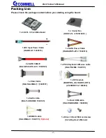
Страница 3: ...0523 1 xUSB2 0 cable OALUSBA 3 1040173 Optional 1 x Audio cable OALPJ HDUNB 1040123 1 x PS 2 Keyboard Mouse cable OALPS2 KM 1040131 1 x Dual COM cable OALES BKU2NB 1040090 1 x SATA Power Cable OALSATA...
Страница 4: ...Power on type selection 12 2 4 I O interface 12 2 4 1 Serial ATA interface 12 2 4 2 Ethernet interface 13 2 4 3 Display interface 13 2 4 4 Serial Port interface 16 2 4 5 USB interface 19 2 4 6 Audio...
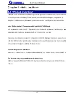
Страница 5: ...tium and Celeron processor families are new generation and multi core processor built on 14 nanometer process It provides new Graphics support 3 independent 4K UHD displays Memory is support up to 16G...
Страница 6: ...ntel UHD Graphics Display Interface 1 x DisplayPort Optional 1 x HDMI 1 x DVI 1 x LVDS 1 x VGA LAN Chip 1 x Intel I219 LM Gigabit PHY LAN Support iAMT12 0 1 x Intel I210 AT Gigabit LAN I O Serial ATA...
Страница 7: ...LS 37L User s Manual 6 1 3 Block Diagram...
Страница 8: ...on and Reference Display Port USB3 1 Gen2 I210 AT I219 LM USB3 1 Gen2 HDMI COM1 CN_SATA3 1 CN_SATA3 2 CN_LVDS CN_CRT DDR4_A CN_PS2 MINI_CARD CN_DVI DC_IN CPUFAN CN_BAT SYSFAN CN_SMBus CN_USB2 2 CN_USB...
Страница 9: ...32 connector CN_USB 2 1 2 2 5 x 2 pin USB2 0 pin header CN_PS2 5 x 2 pin PS 2 pin header CN_DIO 6 x 2 pin digital I O connector CN_SMBus 5 pin SMBus connector CN_BAT 2 pin Battery connector CPUFAN 4 p...
Страница 10: ...S 37L needs RMA please Keep CPU socket cover on the CPU Socket Warning If CPU Socket internal Pin damage We could not provide warranty 1 Lift this bar 2 Uncover this plate 8th generation Intel Core Pe...
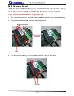
Страница 11: ...frequency supports 2666 MHz Only Non ECC memory is supported In the process the board must be powered off 1 Put the memory tilt into the slot Note the Memory notch key aligned slot key 2 Then press d...
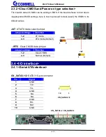
Страница 12: ...Jumper Location and Reference 2 3 1 Jumper list Jumper Function JAT Power mode select JRTC CMOS Normal Clear Setting JVLCD Panel Voltage Setting JMSATA MiniCard mSATA Setting JVUSB USB Voltage Setting...
Страница 13: ...set the CMOS to its default values JAT AT ATX mode select jumper Jumper settings Function 1 2 AT mode 2 3 ATX mode Default RJRTC Clear CMOS data jumper Jumper settings Function 1 2 Clear CMOS 2 3 Norm...
Страница 14: ...lay interface Based on the 8th Gen CPU with built in HD Graphics 630 VGA and DVI up to 1920x1080 60Hz DisplayPort up to 4096x2304 60Hz HDMI up to 4096x2304 24Hz on rear IO About the internal Display L...
Страница 15: ...5VCDA 13 5HSYNC 14 5VSYNC 15 5VCLK 16 NC CN_DVI DVI on board 20 pin connector Pin Signal Pin Signal 1 5V 2 N C 3 HPD 4 Ground 5 TMDSTX0N 6 TMDSTX0P 7 Ground 8 TMDSTX1N 9 TMDSTX1P 10 Ground 11 TMDSTX2...
Страница 16: ...18 A_LVDS_2 17 B_LVDS_2 20 A_LVDS_2 19 B_LVDS_2 22 GND 21 GND 24 A_LVDS_CLK 23 B_LVDS_3 26 A_LVDS_CLK 25 B_LVDS_3 28 GND 27 GND 30 A_LVDS_3 29 B_LVDS_CLK 32 A_LVDS_3 31 B_LVDS_CLK 34 GND 33 GND 36 LVD...
Страница 17: ...7L User s Manual 16 2 4 4 Serial Port interface COM1 DB9 connector Pin Signal Pin Signal 1 DCD 2 RXD 3 TXD 4 DTR 5 GND 6 DSR 7 RTS 8 CTS 9 RI COM1 20 19 2 1 CN_COM3 4 20 19 2 1 CN_COM5 6 CN_COM2 10 9...
Страница 18: ...422TX 485 13 TXD2 14 DTR2 15 GND 16 DSR2 422RX 17 RTS2 18 CTS2 422RX 19 RI2 20 Key COM3 4 RS 232 422 485 can set by BIOS You can find the setting from On Front Page screen click Setup Utility On Adven...
Страница 19: ...al 18 COM5 6 RS232 20 pin header Pitch 2 54 x 1 27mm Pin Signal Pin Signal 1 DCD1 2 RXD1 3 TXD1 4 DTR1 5 GND 6 DSR1 7 RTS1 8 CTS1 9 RI1 10 NC 11 DCD2 12 RXD2 13 TXD2 14 DTR2 15 GND 16 DSR2 17 RTS2 18...
Страница 20: ...erface CN_USB 2 1 2 2 USB2 0 10 pin header Pitch 2 54 mm Pin Signal Pin Signal 1 5VSB 2 5VSB 3 DATA0 4 DATA1 5 DATA0 6 DATA1 7 GND 8 GND 9 GND 10 Key 1 2 5 6 JVUSB CN_USB2 1 2 9 10 1 CN_USB2 2 2 9 10...
Страница 21: ...5V Effective patterns of connection 1 3 2 4 or 3 5 4 6 JVUSB can control USB3 0 RIGHT power 2 4 6 Audio interface CN_AUDIO Front panel audio 10 pin header Pitch 2 54mm Pin Signal Pin Signal 1 MIC_L 2...
Страница 22: ...ve some special design to compatible our mini PCIe card ex MPX 574D2 MPX 210D2 etc MINI_CARD support mSATA by JMSATA JMSATA Setting MINI_CARD to support PCIe mSATA Jumper settings Function 1 2 Support...
Страница 23: ...t panel switch and indicator JFRNT Front panel switch and indicator 14 pin header Pitch 2 54mm Pin Signal Pin Signal 1 Power_ON 2 Power_ON 3 Speaker 4 Speaker 5 HDD_LED 6 HDD_LED 7 Power_LED 8 Power_L...
Страница 24: ...LS 37L User s Manual 23 2 4 9 GPIO and Other interface CN_PS2 CN_DIO 1 2 9 10 1 12 2 11 CN_SMBus 1 5 SYSFAN 1 4 CPUFAN 1 4...
Страница 25: ...value in BIOS PEI phase DXE Phase output value GPIO output value in BIOS DXE phase As Input TTL level GPIO DC characteristics Parameter SYM MIN TYP MAX UNIT Conditions Input Low Voltage VIL 0 8 V Inpu...
Страница 26: ...M_CLK CN_SMBus SMBus 5 pin connector Pitch 2 54mm Pin Signal 1 5V 2 NC 3 SMBDAT 4 SMBCLK 5 GND CPUFAN SYSFAN cooler fan 4 pin connector Pin 1 2 3 4 Signal GND 12V Sensor Control 2 5 Power supply 2 5...
Страница 27: ...LS 37L User s Manual 26 2 5 2 Power output DC_OUT SATA power 4 pin connector Pin Signal 1 12V 2 GND 3 GND 4 5V DC_OUT 1 4...
Страница 28: ...Page screen click Setup Utility 3 On Advenced screen click PCH IO Configuration then click Security Configuration 4 Set BIOS Lock to Disabled then save changes 5 Please make a boot able Disk which co...
Страница 29: ...r panel it need to select the correct resolution in the BIOS If there is no fit your panel type please feedback for us to make OEM modol Find the setting from Front Page Setup Utility Advanced LVDS Co...
Страница 30: ...LS 37L User s Manual 29 Advanced SA configuration Graphics confuguration LCD control LCD Panel Type There are 16 resolutions in LCD Panel Type For Dual boot and Legacy boot...
Страница 31: ...uto reset while it stops to work for a period The integrated watchdog timer can be setup as system reset mode by program You can select Timer setting in the BIOS after setting the time options the sys...
Страница 32: ...ical Device o 4E 30 o 4F 01 activate WDTO function o 4E F0 o 4F 00 set 00 is second mode set 08 is minute mode o 4E F1 o 4F 05 00h Timeout Disable 01h Timeout occurs after 1 minute only 02h Timeout oc...
Страница 33: ...LS 37L User s Manual 32 Appendix D Hardware Monitor Find the setting from Advanced SIO NCT6116D Hardware Monitor...
Страница 34: ...E 07 o 4F 07 select Logical Device o 4E 30 o 4F 10 activate GPIO function The board use GPIO4 o 4E F0 o 4F XX set 01 GPIO as input set 00 GPIO as output o 4E F1 o 4F XX if set GPIO as output this regi...
Страница 35: ...ndix F RAID Setting When use RAID function it need to enter the BIOS set RAID mode first Advanced PCH IO Configuration SATA and RST Configuration SATA Mode Selection At boot time press CTRL I to enter...
Страница 36: ...out our products and service or anything we can help you please don t hesitate to contact with us We will do our best to support you for your products projects and business Taiwan Commate computer Inc...