LP-174
Pico-ITX Motherboard
User’s Manual
Edition 1.3
2016/06/22
Страница 1: ...LP 174 Pico ITX Motherboard User s Manual Edition 1 3 2016 06 22...
Страница 2: ...ent are property of their respective owners Disclaimer The company shall not be liable for any incidental or consequential damages resulting from the performance or use of this product The company doe...
Страница 3: ...nclude Cooler Fan 1 x SATA SATA Power Cable OALSATA22B PM15SH15 1040512 1 x PS 2 Keyboard Mouse cable OALPS2 KM 1040131 1 xDC Input Power Cable OALDC B 1040513 1 x Audio cable OALPJ HDUNB 1040123 1 xU...
Страница 4: ...Power on type selection 10 2 3 Installing the Memory 11 2 4 I O interface 12 2 4 1 Serial ATA interface 12 2 4 2 Ethernet interface 12 2 4 3 Display interface 13 2 4 4 Serial Port interface 15 2 4 5 U...
Страница 5: ...h Haswell U multi core mobile processor built on 14 22 nanometer process with MCP technology The Broadwell U has a lower TDP 15W and 28W it provides new HD Graphics GT2 and GT3 GPU support triple disp...
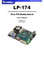
Страница 6: ...pport mSATA Graphics Chipset Intel Gen 8 7 5th integrated HD Graphics Display Interface 1 x DVI D 1 x DisplayPort 1 x LVDS LAN Chip 1 x Intel I218 LM Gigabit LAN Support iAMT10 0 I O Serial ATA 1 x SA...
Страница 7: ...LP 174 User s Manual 6 1 3 Mechanical Drawing...
Страница 8: ...P DDR3L SO DIMM 1 x DisplayPort 1 x DVI D PTN3460 1 x LVDS SIO NCT6102D DDI Channel A eDP DDI 1 x SATA3 SATA3 2 x USB3 0 2 x USB2 0 USB3 0 USB2 0 SPI Flash SPI PCIe x1 I218 LM HDA HD Audio PCIe x1 SAT...
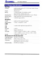
Страница 9: ...ter 2 Hardware setup 2 1 Connector Location and Reference CN_LVDS MINI_CARD CN_LPC CN_AUDIO DC_IN CN_DVI CN_USB CN_PS2 JFRNT DisplayPort USB LAN CN_SATA CN_COM1 2 CN_INV DC_OUT SYSFAN CPUFAN CN_SMBUS...
Страница 10: ...s connector CN_COM1 2 20 pin RS232 connector CN_USB 5 x 2 pin USB2 0 pin header CN_DVI 10 x 2 pin DVI connector CN_PS2 5 x 2 pin PS 2 pin header CPUFAN 3 pin CPU fan connector SYSFAN 3 pin system fan...
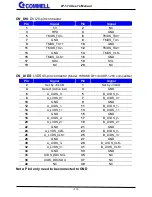
Страница 11: ...rmal Clear Setting JVLCD Panel Voltage Setting JMSATA MiniCard mSATA Setting 2 2 2 Clear CMOS and Power on type selection JRTC Clear CMOS data jumper Jumper settings Function 1 2 Clear CMOS 2 3 Normal...
Страница 12: ...ss the board must be powered off 1 Put the memory tilt into the slot Note the Memory notch key aligned slot key 2 Then press down till lock into the mounting notch 3 To remove the memory push outward...
Страница 13: ...connector 2 4 2 Ethernet interface The board provide I218 LM Gigabit Ethernet which supports WOL on rear I O It supports Intel AMT 10 0 feature Note that the CPU must support vPro technology ex i7 565...
Страница 14: ...internal Display the DVI D resolution up to 1920x1200 60Hz and LVDS PTN3460 up to 1920x1200 60Hz support 18 24 bit color depth and dual channel About select LCD Panel Type in BIOS please refer Appendi...
Страница 15: ...compatible Pin Signal Pin Signal 2 Set by JVLCD 1 Set by JVLCD 4 Detect Active low 3 GND 6 A_LVDS_0 5 B_LVDS_0 8 A_LVDS_0 7 B_LVDS_0 10 GND 9 GND 12 A_LVDS_1 11 B_LVDS_1 14 A_LVDS_1 13 B_LVDS_1 16 GN...
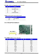
Страница 16: ...ght JVLCD LVDS panel power select jumper Jumper settings Function 1 2 3 3V Default 2 3 5V 2 4 4 Serial Port interface CN_COM1 2 RS232 20 pin connector Pin Signal Pin Signal 1 DCD1 2 RXD1 3 TXD1 4 DTR1...
Страница 17: ...nal 1 5VSB 2 5VSB 3 DATA0 4 DATA1 5 DATA0 6 DATA1 7 GND 8 GND 9 GND 10 Key 2 4 6 Audio interface CN_AUDIO Front panel audio 10 pin header Pitch 1 27mm x 2 54mm Pin Signal Pin Signal 1 MIC_L 2 GND 3 MI...
Страница 18: ...Setting MINI_CARD to support PCIe mSATA Jumper settings Function 1 2 Support mSATA 2 3 Normal operation Default 2 4 8 Front panel switch and indicator JFRNT Front panel switch and indicator 14 pin hea...
Страница 19: ...AD1 7 LAD0 8 3 3V 9 SERIRQ 10 GND 11 3 3VSB 12 NC Note Support TPM module CN_SMBUS SMBus 5 pin connector Pin Signal 1 5V 2 NC 3 SMBDAT 4 SMBCLK 5 GND CPUFAN CPU cooler fan 3 pin connector Pin 1 2 3 Si...
Страница 20: ...r input The power support 9 24V wide voltage input DC_IN Terminal Block 2 pin power connector Pin Signal Pin Signal 1 GND 2 Power in 2 5 2 Power output DC_OUT SATA power 6 pin connector Pin Signal 1 1...
Страница 21: ...FPT10 rar The tool s file name is fpt exe it s the utility that can write the data into the BIOS flash chip and update the BIOS A 2 Flash BIOS process 1 Please make a bootable UFD which can boot into...
Страница 22: ...us download details aspx id 38423 B 2 USB3 0 driver Before Win7 install the USB3 0 driver or use in Win8 and Win8 1 xHCI needs to be enabled in the BIOS Note that if enable xHCI all USB port will unus...
Страница 23: ...s to make OEM modol BIOS panel type selection form BIOS Version 1 0 Single Dual channel Single Dual channel NO Type NO Type 1 640 x 480 9 1680 x 1050 2 800 x 600 10 1920 x 1200 3 1024 x 768 11 1440 x...
Страница 24: ...7 o 4F 08 select Logical Device o 4E 30 o 4F 01 activate WDTO function o 4E F5 o 4F 00 set 00 is second mode set 04 is minute mode o 4E F6 o 4F 05 00h Timeout Disable 01h Timeout occurs after 1 minute...
Страница 25: ...o our best to support you for your products projects and business Taiwan Commate computer Inc Address 19F NO 94 Sec 1 Xintai 5th Rd Xizhi Dist New Taipei City 22102 Taiwan TEL 886 2 26963909 FAX 886 2...