background image

About this manual 


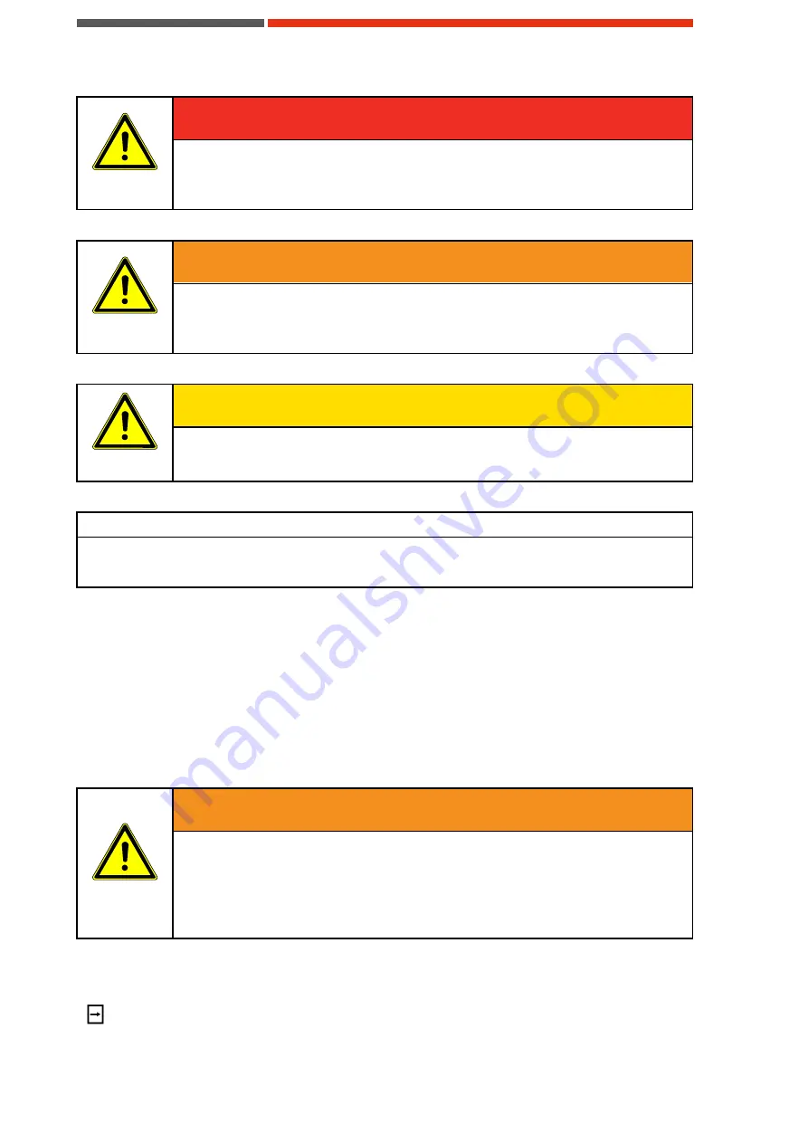
DANGER 

DANGER 

Reference to immediate danger to human health. 

Failure to comply with this warning instruction will result in severe irreparable injury 
and even death.


WARNING 

WARNING


Reference to recognizable hazard to human health. 

Failure to comply with this warning instruction may result in severe irreparable injury 
and even death.


CAUTION 

CAUTION 

Reference to recognizable hazard to human health. 

Failure to comply with this warning instruction may result in slight to medium injury. 


NOTE


Reference to a material hazard. 

Failure to comply with this warning instruction may result in material damage. 

Structure of the warning instructions


The following information builds the warning instructions: 

  Warning symbol 

  Signal word 

  Type and source of the hazard 

  Causing 

  Measure(s) to avoid the hazard 

Example:


WARNING 

WARNING 

Risk of burning and/or scalding due to possibly hot coolant. 

Coolant can reach high temperatures during operation and cause burns or scalding 
in the case of contact. 

Check whether the coolant is hot before handling it. If necessary, let it cool down to 
the ambient temperature, that there is no more risk of burns or scalding. 


Important information and tips concerning operation of the unit


This symbol is used to highlight passages with important information and tips concerning operation 
of the unit. 

Содержание XRCA-3023-WA

Страница 1: ...Industrial X Ray Chiller Manual XRCA 3023 WA 3000 Watt Water to Air Chiller...

Страница 2: ...ing of this document utilization or posting of its contents is not permitted unless formally granted Violations entail claims for compensation All copyrights including rights due to patent grant or re...

Страница 3: ...t operator 12 2 2 1 Planning and monitoring the safety measures 12 2 2 2 Minimizing the risk of injury 12 2 3 Personnel requirements 12 2 3 1 Qualifications 12 2 3 2 User groups 13 2 3 3 Specialized k...

Страница 4: ...it 25 5 9 Preparing the unit for the further transport 25 6 INSTALLATION AND COMMISSIONING 27 6 1 Requirements concerning the installation location 27 6 1 1 Installation location 27 6 1 2 Environmenta...

Страница 5: ...Cleaning the heat exchanger 44 9 11 Cleaning the casing 45 10 REPAIR 46 10 1 Safety 46 10 2 Repair procedures 46 11 DECOMMISSIONING AND DISPOSAL 47 11 1 Temporary placing out of operation 47 11 2 Ret...

Страница 6: ...pect to general danger or damage to property Warning with respect to electrical hazard Table 1 Warning signs Symbol Meaning This symbol indicates the requirement of disconnecting from mains This symbo...

Страница 7: ...is warning instruction may result in material damage Structure of the warning instructions The following information builds the warning instructions Warning symbol Signal word Type and source of the h...

Страница 8: ...warranty and duration of warranty of the unit in question can be taken from the contract documents as well as from the order confirmation Warranty claims and liability are excluded in case of one of t...

Страница 9: ...tional equipment it is the sole responsibility of the customer to assure the accurate implementation of the safety devices required 1 4 Contact information If you have questions with respect to this u...

Страница 10: ...the operational location of the unit in a complete and perfectly readable form Use the unit exclusively for what it was intended The unit must be operational and error free Check the condition of the...

Страница 11: ...ns is not permitted since otherwise the operation safety cannot be granted When using the unit in a way not compliant with the intended use hazardous situations may occur Operation of the unit is not...

Страница 12: ...available for first aid and rescue operations The procedures competence and responsibility have to be determined Employees have to practice the procedures to be followed in the event of an incident Al...

Страница 13: ...of the structure and functionality of unit Table 3 User groups 2 3 3 Specialized knowledge NOTE Authorized persons The technical information about the unit settings maintenance and electrics is direc...

Страница 14: ...ng of coolant 2 5 Safety and signaling equipment included in the unit The unit is equipped with the following safety equipment see Figure 1 The maximum pump pressure is limited by a pressure relief va...

Страница 15: ...or the purpose of maintenance or repair works and shall be replaced prior to taking the unit back into operation see Removing and mounting the unit cover 2 7 Caution label Danger spots on the unit are...

Страница 16: ...nvironmental issues And anticipatory behavior of staff avoids environmentally hazardous impacts The following principles apply for environmentally conscious behavior Environmentally hazardous substanc...

Страница 17: ...or COMET Type of product 3000 watt water to air chiller Type of unit XRCA 3023 WA 3 2 Identification plate The identification plate is attached to the housing of the unit and contains the following sp...

Страница 18: ...mitted since otherwise the operation safety cannot be granted When using the unit in a way not compliant with the intended use hazardous situations may occur Operation of the unit is not permitted und...

Страница 19: ...rounding air driven by the fan through the heat exchanger 4 4 2 Cooling circuit secondary circuit In the cooling circuit the coolant is moved by the pump via the supply line to the target device and b...

Страница 20: ...nit operational frost guard did not trigger Off frost guard triggered unit cannot be activated Key DOWN Lowers the value of the selected parameter incrementally Key UP Raises the value of the selected...

Страница 21: ...Current consumption 9 3 A Operating noise 65 dB A measured at a distance of 1 m Air flow at 50Hz 60Hz 1700 m3 h 2200 m3 h Protection class IP21 Environment specifications Operation above sea level Up...

Страница 22: ...e mounting suspensions of different components inside the unit are not secured with transporta tion locks In case of improper transportation these can be damaged without repair and would need to be re...

Страница 23: ...and recycled Dispose of packing materials environmentally Follow the locally valid waste disposal regulations If necessary employ a special waste disposal company to dispose of packing material The un...

Страница 24: ...ns Secure the unit so that it cannot tip or fall For in house transport lift the unit and transport it by means of suitable industrial truck or lift truck 5 7 Transportation on rollers The unit is equ...

Страница 25: ...ion caps for the coolant inlet and coolant outlet connections have only to be removed just before installation takes place In order to store the units for more than 6 months please consult COMET 5 9 P...

Страница 26: ...over removed see Removing and mounting the unit cover Tools and material required Slot screwdriver Procedure Dismount the vent plug Mount the transport plug using the slot screwdriver Mount the unit c...

Страница 27: ...osion damage may result and are not covered by manufacturer s liability The unit is only authorized for use in indoor environments The unit must not be stored or operated in aggressive humid environme...

Страница 28: ...tch off the unit before starting your work Disconnect the unit from mains by pulling the mains plug Secure the unit against being switched on again Verify that the unit is dead Carry out earthing and...

Страница 29: ...up of the unit NOTE Lack of coolant may impair cooling capacity and destroy the pump Only operate the unit with correct coolant level Check the coolant level regularly Starting up the unit Requirement...

Страница 30: ...t Switching off the unit Requirements Cooling operation finished Procedure Switch of the unit using the power button Close all valves that may exist in the extension of the hoses running to and from t...

Страница 31: ...department to receive a briefing NOTE The maximum pressure which is reached by the device to be cooled is affected by the length of the coolant hoses Setting the maximum pressure Tools and material re...

Страница 32: ...olant outlet temperature is now set 7 3 3 2 Setting the anti freeze guard T2 NOTE By default the nominal value of the anti freeze temperature is set to 5 C by factory It is stored in the internal para...

Страница 33: ...OWN simultaneously and hold for 4 seconds The display shows P1 Press the SET key and hold it during adjustment Set up mode is now activated and the current value of P1 is displayed Set the desired val...

Страница 34: ...n or an extended cooling circuit with long hoses Heat exchanger condenser polluted Fan polluted or blocked Filter strainer in a closed hydraulic circuit polluted or blocked More help can be found in t...

Страница 35: ...Cleaning the filter strainer Operator No flow in cooling circuit Flow is signaled potential free by the safety equipment of the unit and can be indicated by the controls of the device to be cooled Ope...

Страница 36: ...ing on electrical installations the following principles should be observed Works on the electrical installations may only be accomplished by qualified electrical staff When connecting electrical equi...

Страница 37: ...ling or tipping over Only perform maintenance work using conventional tools Improper or dam aged tools can result in personal injury Handling with coolant WARNING WARNING Risk of burning and or scaldi...

Страница 38: ...tenance task Personal protective gear The following personal protective gear for all maintenance work has to be worn Protective footwear Protective gloves Protective eyewear 9 2 Maintenance schedule T...

Страница 39: ...o be made Terminate the cooling operation Let the unit and its coolant cool down to the ambient temperature Switch off the unit Disconnect the unit from mains by pulling the mains plug Secure the unit...

Страница 40: ...e that non transparent hoses are used to prevent algae growth in the water Otherwise appropriate additives have to be used NOTE When connecting the coolant hoses pay attention to flow direction Follow...

Страница 41: ...nd material required Collection container Filling funnel Absorbent cloth Bonding agent Procedure Connect the hose nipple to the coolant outlet Place a suitable container below the coolant outlet to co...

Страница 42: ...on of the coolant filler plug 1 Vent plug 2 Transport plug 3 Coolant filler opening 9 8 Removing and mounting the unit cover NOTE The connection side and the back side of the unit may not be removed R...

Страница 43: ...o the ambient temperature that there is no more risk of burns or scald ing NOTE Risk of damage to the pump if the unit is operated with a fully closed ball valve Never start the unit when the ball val...

Страница 44: ...l and top up if necessary see Adding coolant Start up the unit see Putting the unit into operation The filter strainer is now clean Figure 12 Mounting position of the filter strainer 1 Screw cap of th...

Страница 45: ...ay Hand brush Brush Procedure Clean the heat exchanger with a vacuum cleaner hand brush or brush Clean the heat exchanger with compressed air opposite to the direction of air entrance into the unit i...

Страница 46: ...g the warranty period the unit must be sent to the COMET service department for repair see Contact information or the COMET services website under http www comet xray com Service Contact Form When war...

Страница 47: ...free room For recommended storage conditions see Storing the unit Prior to decommissioning Procedure Finish the cooling operation Disconnect the unit from mains Let the unit and the coolant cool down...

Страница 48: ...operating materials of the unit can be hazardous to the environment and to health Make sure the operating materials are disposed of or recycled according to local regu lations Also the safety specific...

Страница 49: ...f spare parts made by manufacturers other than COMET The type of the unit and the article number can be found on the identification plate of the unit The corresponding numbers shown in drawings below...

Страница 50: ...Addendum 50 13 Addendum 13 1 Performance diagram Item Position Designation T C Temperaturedifference Oil to water W Cooling performance in watts 1 Ambient temperature...

Страница 51: ...Addendum 51 13 2 Flow chart...

Страница 52: ...ion line accumulator C Bypass valve 3 Compressor D 1 Evaporator 4 Pressure controller LP HP E Temperature controller 5 Check valve F Level sensor 6 Condenser G Container 7 Collector H Filter 8 Shut of...

Страница 53: ...Addendum 53 13 3 Wiring diagram...

Страница 54: ...rigerating unit M3 Fan N1 Temperature controller N1T1 Forward temperature N2T2 Temperature max N1T3 Antifreezing Q1 Relay refrigerating unit Q2 Disturbance level relay Q3 Relay R1 RC element R2 RC ele...

Страница 55: ...Addendum 55 13 4 Dimension drawing...

Страница 56: ...ch www comet xray com USA COMET Technologies USA Inc 100 Trap Falls Road Extension Shelton CT 06484 USA T 1 203 447 31 65 F 1 203 925 03 64 service xray cometusa com www comet xray com Asia COMET Chin...

Отзывы: