ID-Mobile Global Guide
239
1. Rename the output.
2. Adjust regulation period. The period should be adjusted according to the speed of the
response of the system, e.g. longer period for slower systems, shorter period for
faster systems.
3. You may want to have some regulation parameters, as e.g. derivative part or bias,
constant. In such a case write the constant directly into the appropriate box. If there is
a source configured, it must be deleted prior to writing of the constant.
4. If you need the regulator to run only if certain condition is fulfiled, use the gate input.
Create a binary value representing the condition (e.g. using other plc blocks) and
connect it to the gate input. The regulator will then work only if the gate input is active.
If the gate input is not connected, the regulator works all the time the controller is
switched on.
Note:
The inputs are assigned to their sources in the sheet by
dragging a wire
from the
input to the source.
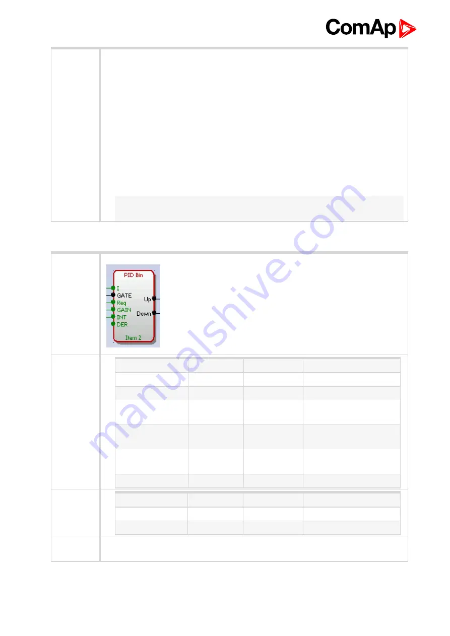
PID regulator with up/down binary outputs
Symbol
Inputs
Input
Type
Range[DIM]
Function
Input
A
Any
Regulated value
Requested val.
A
Same as 'Input'
Required value
Gain
A
-100.00..100.00
[%]
Gain of the regulator
Int
A
-100.00..100.00
[%]
Integrative part of the
regulator
Der
A
-100.00..100.00
[%]
Derivative part of the
regulator
Gate
B
N/A
Regulator on/off input
Outputs
Output
Type
Range[DIM]
Function
Output up
B
N/A
Actuator control - Raise
Output down
B
N/A
Actuator control - Lower
Description
The block is a PID regulator with binary outputs up/down and adjustable regulation period.
The function of the regulator can be disabled by the gate input.


