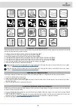
ASSEMBLING THE BRUSH HEAD BODY BRUSHES
To fit the brush on the brush head body, proceed as follows:
1. Take the machine to the maintenance area.
2. Make sure the machine has been secured (see the chapter entitled
).
CAUTION
: it is recommended to wear the appropriate PPE (Personal Protective Equipment) for the work to be carried out
.
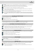
3. Go to the left-hand side of the machine and remove the left-hand carter (
Fig.15
). Unfasten the retainers on the carter before removing it (
Fig.16
).
4. Insert the front brush into the tunnel, taking care to make sure that the gearmotor drive shaft enters the slit in the brush itself.
5. Repeat the operation described for the rear brush.
6. Fit the left-hand carter and secure in place using the retainers loosened previously.
N.B.
: In order to be installed correctly, the brushes must form an X when viewed from above in the forward direction of movement. To facilitate
this operation, the rear brush is equipped with a cusp shaped device in a different colour.
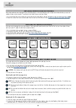
FITTING THE SIDE BRUSH (OPTIONAL)
To fit the brush on the side brush head body, proceed as follows:
1. Take the machine to the maintenance area.
2. Make sure the machine has been secured (see the chapter entitled
).
CAUTION
: it is recommended to wear the appropriate PPE (Personal Protective Equipment) for the work to be carried out
.
3. Go to the right side of the machine.
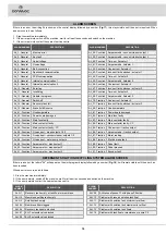
4. With the brush head in the raised position, insert the brush into the brush holder plate (
Fig.17
). Rotate the brush unit the brush's three buttons
on the brush, grip with the notches in the brush plate.
5. Turn the brush in increments until the button is pushed towards the coupling spring and is locked in place (
Fig.18
).
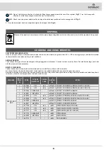
USER SEAT ADJUSTMENT
The proper adjustment of the driving position provides a greater sense of comfort when using the machine.
Seat backrest adjustment
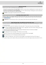
: make sure you sit upright and that your back and lower back and spine are at 90°. Use the lever on the left side of the seat
(
Fig.19
) to adjust the backrest of the seat.
Driving position adjustment
: The seat should always be positioned using the pedals as a reference. Use the lever in the lower part of the seat (
Fig.20
) to
adjust the seat.
N.B.:
The distance should be adjusted so that with the pedals fully pressed to the floor the knees are slightly bent (about 120°).
N.B.:
Adjust the distance of the seat so that when pressing the brake pedal it goes as far as it can. This operation should be done with the machine
running so as to pressurise the braking system.
N.B.:
If the knee is not bent enough, it is too far from the steering wheel, if however the knee is bent almost 90°then it is too close to the steering
wheel.
N.B.:
The feet should be positioned keeping the heels on the footrest, the sole of the foot directly below the fingers should push the pedals.
N.B.:
The ideal driving position is that which allows you to grip the steering wheel correctly with the palms slightly lower than the shoulders. With a
good grip on the steering wheel, the elbows should be bent by about 120°. They should be at least 30 cm or 11.81 in between the middle of the
steering wheel and our breastbone. In any case, this distance should be no more than 45 cm or 17.72 in.
Adjusting the armrests (optional):
the armrests should be inclined to make using the machine comfortable.
N.B.:
To adjust the armrest, use the wheel underneath it (
Fig.21
).
N.B.:
Taking the right armrest as a reference, if the wheel is turned outwards the inclination of the armrest is increased. Taking the left
armrest as a reference, if the wheel is turned inwards the inclination of the armrest is increased.
CAUTION
: it is recommended to wear the appropriate PPE (Personal Protective Equipment) for the work to be carried out
.
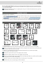
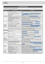
3.
Close the tap output flow and turn the lever positioned near the operator seat in a clockwise direction (
Fig.13
).
4.
Insert the filter cartridge in the housing on the cap (
Fig.14
).
N.B.:
The O-ring gasket in the filter cartridge should be inserted into its seat in the cap.
5.
Screw the cap onto the body of the detergent solution filter (
Fig.7
).
14


