background image


 Page | 36  


VASTRAJET 

 8. Head Installation  

Use this section, if Print Head is not installed in the printer. 

The installation of Print Heads is to be done only by a service engineer. If the Print Head is not installed 
correctly, it can affect the printing quality. 

Note: Don’t apply much pressure on 

Print Head

 while handling it. 

Follow these steps to install the Print Head: 

Step 1

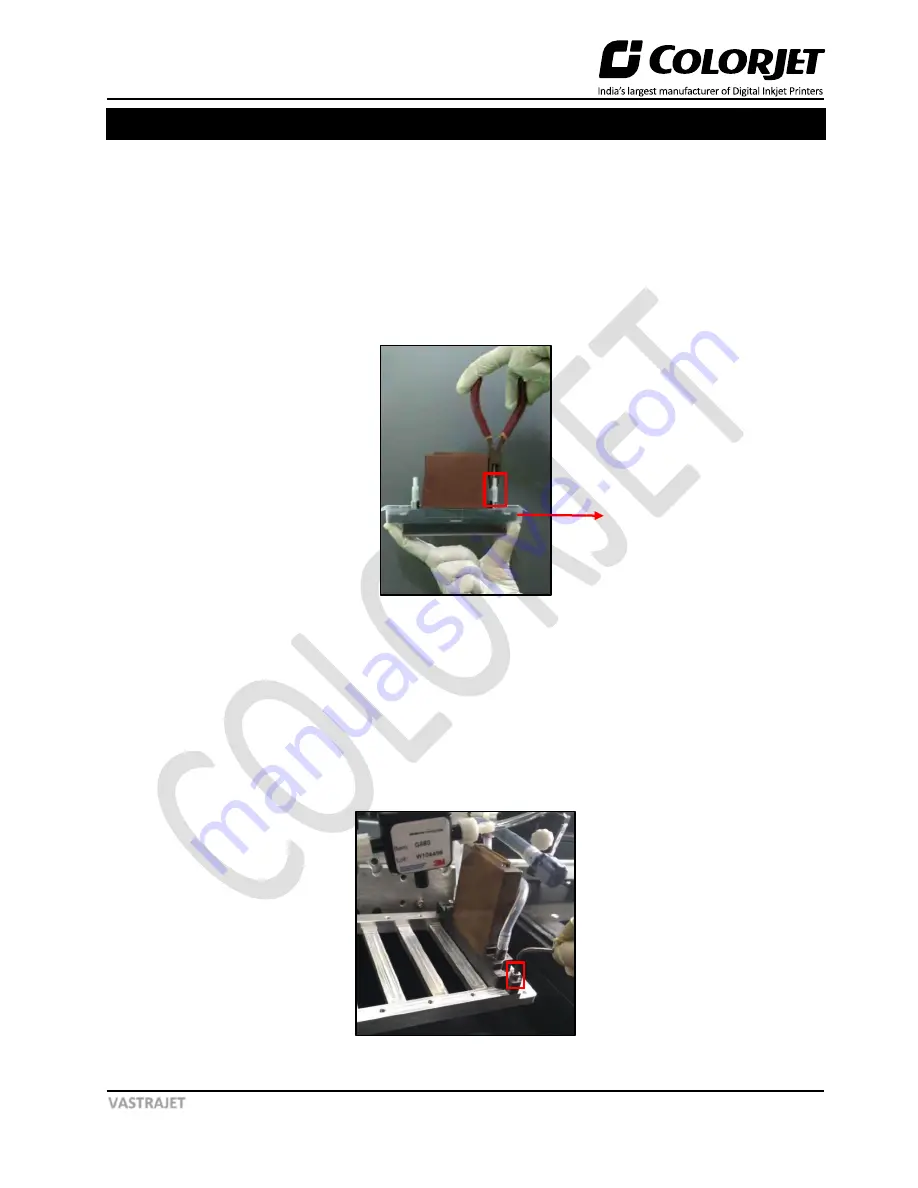
: Remove the 

Ink Inlet caps 

gently to avoid damage to the Print Head, as shown below: 


Fig 40: Removing the Ink Inlet Caps 

Step 2: 

Fix the 

Air Releasing pipe

 on one end of the 

Ink Inlet Tube 

(Refer to Fig 41). 

Step 3: 

Remove the 

Nozzle Cap

 from the Print Head (Refer to Fig 41). 

Note: 

Don’t put the Print Head (nozzle facing) on the rough or dusty surface.


Step 4: 

Mount the 

Print Head

 in the slot on the 

Head Plate

.  

Step 5: 

Fix all the screws (

3x16 mm screws

) gently on the Print Head, as shown below: 


Fig 41: Fixing the Head Screw 

Nozzle Cap 

Содержание Vastrajet

Страница 1: ......

Страница 2: ...TRAJET machine without anyone else assistance The information provided in this document ensures its uniqueness and language quality For safe and proper use of the product please read this document car...

Страница 3: ...ements 11 4 Unloading and Unpacking 12 Packing Details 12 Tool Requirements 12 Unloading and Unpacking the Machine 12 5 Getting Ready the Machine 14 6 Installing Accessories 15 Levelling the Machine 1...

Страница 4: ...lue Removing Preparation 32 7 Ink Filling 35 8 Head Installation 36 9 Installation of Printer Manager 38 Printer Manager Settings 41 Head Voltage Settings 43 10 Loading the Fabric 46 11 Head Alignment...

Страница 5: ...out of the printer is shown as below Fig 1 Displaying the Site Layout Machine Dimension 3810 x 1780 x 1640mm Length x Width x Height 1 Waste Water Outlet 1 BSP 4000 Liters Per Hour 2 Low TDS 10 40 PPM...

Страница 6: ...e the level or degree of danger or damage that may be caused by ignoring the sign and mishandling the product Warning Indicates a situation that can potentially result in death or serious injury Cauti...

Страница 7: ...g may cause a fire Following must be observed Remove dust and debris from the plug before putting it into the outlet Do not put the power switch at wet place Do not insert or drop metal or flammable o...

Страница 8: ...stalling the product on the wall side then make sure that there is sufficient distance between the product and wall For safety purpose make sure that turn the power switch OFF unplug the switch and re...

Страница 9: ...as not been used for more than a weak to avoid print head nozzle blockage Don t apply more pressure while installing the main or sub ink tanks as it can cause ink leakage damage the machine or contami...

Страница 10: ...g or piling up Avoid direct sunlight When storing printed fabric follow the instructions that came with fabric to avoid color change Precautions for Ink Use Ink Before Use Carefully observe the follow...

Страница 11: ...ttage 2500Watts peak load 20 20Volts AC 50Hz Sinewave Max 3000Watts o Continuous 5 Sec break acceptable in 60 Secs power supplies required o Safety 32A MCB must be used to Power this Inlet Power Inlet...

Страница 12: ...s 10 OS Human Input Devices Keyboard Mouse HDD SSD 500GB or more 1 USB 2 0 Port or USB 2 0 Compatible USB 3 0 for VastraJet Interface Color monitor with 1600x1024 resolution 24 bit Colors Environment...

Страница 13: ...p pipes water tank will be enclosed with the machine Tool Requirements The Tool Requirements for unloading and unpacking are given as follow Fork lift Hydra Crane Spanner 10 mm 17 mm and 24 mm Wire Cu...

Страница 14: ...ropes must be tied just near to pallet mounting holes and strictly not near the extreme ends of the lower cabinet Upper cabinet should be secured with foam below the tied ropes Step 9 While the machi...

Страница 15: ...inutes Step 12 Check the adhesiveness of glue If glue coating is damaged during unloading and unpacking then again recoat the glue and wait for 4 hours to get it dry Initially glue coating is done by...

Страница 16: ...own below Fig 3 Displaying the Leveler Step 3 Similarly fix all the four levelers in the machine Now the levelers get fixed and all the machine weight lies on these levelers Tube Light Follow these st...

Страница 17: ...ight in the given space as shown below Fig 5 Fixing the Tower Light Step 2 Tight the screws to fix the tower light as shown below Fig 6 Fixing the Screws Step 3 Fix the Tower Light Connector to make t...

Страница 18: ...nts Please confirm that sponge must be wet or soft In case it is not soft then gets it soak with the running water Actuator block gets stuck then adjust the trolley wheels Carefully insert the Washing...

Страница 19: ...idifier pipe in the Humidifier as shown below Fig 9 Displaying the Humidifier Note Humidifier Control knob should set in minimum Step 2 Insert the Humidifier s cables in the Red Black terminal as show...

Страница 20: ...ower Cable Step 1 Remove the Power Cable that comes with the accessory box of the printer Step 2 Connect the AC adapter to the machine s AC inlet located on the right side at the back of the machine a...

Страница 21: ...nect to the machine and the power outlet Turn ON the Machine Turn the Main Power knob located on the right side at the back of the machine to On position as shown below Fig 12 Turning ON the Machine T...

Страница 22: ...tments Follow the instructions to adjust the belt position 1 During printing belt position has to be monitored time to time If the belt shifting has crossed 5mm outside the roller then print has to be...

Страница 23: ...these steps to check the belt movement Step 1 Switch ON the Conveyor Belt Step 2 Initially run the Conveyor belt in slow speed to check for any obstacle and then run the Conveyor Belt for a long time...

Страница 24: ...outside the roller print has be stopped immediately and belt has to be repositioned in center by loosening the tensioner screws else severe damage to belt can happen If you feel unconfident about doin...

Страница 25: ...these steps to run the Wash Cycle Step 1 Switch ON the printer from the main power panel the Start Up screen appears on HMI Step 2 Select the OPERATIONS option from the HMI screen as shown below Fig...

Страница 26: ...The WASHING CYCLE screen appears Refer to Fig 19 Step 4 Enter the BELT SPEED and CYCLE TIME in the given fields Step 5 Enable the WASHING ON option by selecting the WASHING OFF button Step 6 Select th...

Страница 27: ...ting the glue according to the temperature variation Perma It is the final glue coat to make the belt sticky for the fabric Solvent Cleantek This liquid solution is used for the renewing refreshing th...

Страница 28: ...onths whole process has to be repeated after removing existing Glue layers Note Average consumption for the Cleantek solvent is 500ml for one time Approximate consumption of chemicals for a year Prima...

Страница 29: ...masking PVC tape on both edges of the Conveyor Belt by simultaneously moving the belt through HMI in slow speed Fig 23 Using Masking Tape Step 5 Put on gloves goggles and face mask for safety Fig 24 U...

Страница 30: ...able for use and complete process may be required to be repeated 3 persons will be required for this process Follow these steps to start the glue coating process Step 1 Put the Press Roller down Fig 2...

Страница 31: ...ring the Glue Step 4 Let the two persons hold the Press Roller firmly so that it doesn t move Fig 28 Closing the Press Roller Step 5 Once the glue has crossed the press roller speed can be increased t...

Страница 32: ...g of cleaner liquid Step 9 Once the glue seems to be deactivated stop spraying liquid and do simultaneously and quickly below steps Slightly rotate the Press Roller in opposite direction to move the s...

Страница 33: ...o be repeated for every glue coat process Glue Removing Preparation Prepare and ready the following below mention things before removing glue Prepare proper ventilators Wear proper safety armament to...

Страница 34: ...glue on the belt Follow these steps to remove glue Step 1 Prepare cleaner which is dedicated to using glue Step 2 Wipe cloth or paper towel with purified water Place wipe clothes on belt to cover belt...

Страница 35: ...purified water onto the belt Step 8 Wipe out cleaner on the belt by paper towel Fig 36 Wiping Out Cleaner from the Belt Step 9 After clean up the part turn belt and repeat cleaning until clean up ove...

Страница 36: ...the printer four on each side Ink in the Main tanks is pumped to the Sub Ink Tanks located at the Carriage Assembly Follow these steps to fill ink Step 1 Open the back cover of the printer Step 2 Rem...

Страница 37: ...all the Print Head Step 1 Remove the Ink Inlet caps gently to avoid damage to the Print Head as shown below Fig 40 Removing the Ink Inlet Caps Step 2 Fix the Air Releasing pipe on one end of the Ink I...

Страница 38: ...p of the Print Head by following the arrow mark Note While inserting the head cable the machine must be Switch OFF Step 11 Similarly insert the second end of the head cable on the Head Board The block...

Страница 39: ...nstalled USB Driver Let s discuss the installation process in details Follow these steps to install the printer manager software Step 1 Insert the installer CD of the printer manager in the CD ROM The...

Страница 40: ...ears Step 4 To confirm the printer manager installation click on the Next button in the Confirm Installation window The User Account Control window appears on the screen Step 5 Click on the Yes button...

Страница 41: ...ep 7 Click on the Close button to close the window and complete the installation process Refer to Fig 45 Now the Printer Manager software is installed on your system and a shortcut for the Printer Man...

Страница 42: ...the white space in the image during printing o Step Time Set time interval of the feed motor during printing o Job Space Set space between multiple jobs o Feather Select the type of feather effect and...

Страница 43: ...suing the Print command o Idle Spray Spray during carriage at home position This option must be enabled o Spray Before Print This option works with the Print Pre spray Time option When enabled one can...

Страница 44: ...ng path as shown in the image below Fig 50 Selecting the Real Setting Option The Temperature window appears on the screen Step 2 Enter the left and right base voltage values of each color Print Head u...

Страница 45: ...ollow 1RA 5 3 1LA 5 2 1RB 4 6 1LB 4 3 The left and right base voltage values of each color Print Head must be matched with the values printed on the same color Print Head The Left and Right Base Volta...

Страница 46: ...Displaying the Head Voltage Printed on the 1024i Head Step 3 After specifying the head voltage click on the Apply To Board button and then on the Ok button to apply the settings Refer to Fig 52 Now t...

Страница 47: ...p of knob Step 4 Remove the roller stopper pin and place the supply roller into the rear of the machine as shown in the image below Fig 55 Placing thee Supply Roller into the Rear Step 5 Pull out the...

Страница 48: ...rint Dryer and the Stretcher Rollers Step 10 Insert the Empty Core into the Take Up roller with core holders at both edges Step 11 Attach the falling edge of the fabric to the core by sticking evenly...

Страница 49: ...ated to ensure good printing quality To open the Calibration Wizard click on the Main Menu Tools Calibration Wizard path as shown below Fig 58 Selecting the Calibration Wizard Option This should bring...

Страница 50: ...with the help of tools provided The list of mechanical checks are given as below Angle Check Vertical Check When you press the Next button you are redirected to the Calibration Wizard as shown in the...

Страница 51: ...ecks the mounting angle of all the Print Heads Print Heads should be mounted at exactly 90 degrees to the carriage scan direction In the figure below when the Print Heads are mounted correctly at 90 d...

Страница 52: ...l disturb the angle check or vertical check Thus repeat the mechanical check until the perfect alignment condition is achieved After performing the above mechanical checks please verify the results of...

Страница 53: ...t Calibrations Left to Right Calibration is performed to achieve dot placement accuracy of all colors Black Cyan and Yellow with respect to Magenta during the carriage s left to right print sweep Simi...

Страница 54: ...Page 53 VASTRAJET The Left Calibration Result is shown in the image below Fig 65 The Horizontal Left Check The Right Calibration Result is shown in the image below Fig 66 The Horizontal Right Check...

Страница 55: ...ove figure you get the accurate step adjust correction value The correction value is either positive or negative If the value is positive then add it in the current step adjust value for the Print Hea...

Страница 56: ...e settings to the printer click on the Main Menu Setting Save To Printer path as shown below Fig 69 Selecting the Save To Printer Option On clicking the Save To Printer option all the previously made...

Страница 57: ...the Print Heads immediately after purging 15 Water tank filter plates should be cleaned every hour to remove stuck threads and also to avoid overflow 16 If negative pressure is increasing fluctuating...

Страница 58: ...empty 11 Don t switch OFF the printer a Without making the tub down b Without closing the finger valve 12 Don t leave the Print Heads without capped and pulling the sponge tray 13 Don t move the carr...

Страница 59: ...ace it if required Case 2 Servo Driver not ON or faulty a Check the Red LED on Servo Driver if LED is not glow then check the power connection and trace the fault b In case machine is not initialized...

Страница 60: ...e and small size images for printing Case 3 Connect the ground wire to the system Case 4 Check and Replace Encoder Scale Case 5 Replace the Pulley or carriage Belt Case 6 Correct the ripped file error...

Страница 61: ...nnection Case 6 Check input and output power at relay and relay connection Heater Not Working 1 Inlet power not connected or MCB trip 2 Heater coil thermistor thermo stat circuit is open 3 24 V Input...

Страница 62: ...set at Low and Take Up regulator not working Case 1 Loose connection in Servo Driver and PLC Case 2 Remove the Take Up roller and observe it s movement Case 3 Check the regulator settings and rotate t...

Страница 63: ...Case 3 Check the following 1 Check Actuator proper elevation refer to the Washing Tub Not Engaging Properly section 2 Actuator blot is not aligned properly align it Case 4 Refer to the Heater Not Work...

Страница 64: ...ainst current time limit password Request for a new time password from the dealer 0402000D Second Warning 50 hours left against current time limit password Request for a new time password from the dea...

Страница 65: ...language matching password again Please reset the software language or input the new language matching password again 4002001C PINCONF writing FPGA errors Main Board is faulty 40030000 USB communicat...

Страница 66: ...ng value when perform electrical adjustment ALE 13 ALE d Emergency Stop Activated Emergency stop is activated ALE 14 ALE E Reverse Limit Switch Error Reverse Limit Switch is activated ALE 15 ALE F For...

Страница 67: ......

Страница 68: ...For Any Query Please Contact Us www colorjetgroup com Call us on 91 120 4548195 Email on info colorjetgroup com For Ink Enquiry sales colorjetgroup com For Support support colorjetgroup com...

Отзывы: