COFFE
tek
LTD
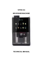
VITRO X3
Issue 1
23/02/17
14
Circuit Description
29.
If the beverage machine is supplied by a 230V~ single-phase supply from a 10A or 16A
outlet (or from a 13A domestic outlet), only one heater can be connected in circuit a 15A
fuse protected heater circuit, a solid state relay (SSR) contact and high temperature cut-out
is placed in the circuit of heater, there is one circuit to protect the Instant boiler and the
same to protect the Espresso boiler.
30.
The SSR switches the supply to the heaters as directed by the MPU Controller in response
to data received from the temperature sensor part of the temperature/level probe for the
Instant boiler and purely the temperature probe for the Espresso boiler, thus maintaining
the water in the boiler at the correct temperature. However, if the water in the boiler starts
to boil, the high temperature cut-outs remove the supply to the heaters. A reset button for
the Instant cut-out is accessible at the top of the machine and the Espresso boiler cut-out is
accessed by removing the left hand side panel and depressing the cut-out directly on top of
the boiler.
31.
A 230V~ ac main supply is taken from terminal block to the Power Supply PCB via the
on/off switch. The Power Supply PCB provides DC supplies of 24V, 12V and 5V. The 24V-
dc output supplies the ingredient motors, whipper motors, extract fan, SSR and solenoid
operated valves. The 12V-dc output supplies the MPU Controller Board and operational
coin acceptor (if fitted).
32.
The MPU Controller Board continually checks the status of input devices connected to
plugs J1 and J3, and responds to any change of state by signalling the operation of the
relevant output devices via on-board current drive transistors. Thus, for example, the water
level probe controls the operation of the inlet valve and the temperature sensor controls the
operation of the SSR.
33.
The dispensing of a beverage begins with the keypad selection, which is scanned by the
MPU Controller Board via a ribbon connector. Control Signals corresponding to the
required actions are then generated by the MPU Controller to operate the relevant output
devices in the correct sequence and for the specified duration. Operator data information is
sent in parallel form to the (LCD) Display.
Содержание VITRO X3
Страница 1: ...VITRO X3 BEVERAGE MACHINE TECHNICAL MANUAL ...
Страница 5: ...COFFEtek LTD 5 23 02 17 Issue 1 VITRO X3 This page is intentionally blank ...
Страница 61: ...COFFEtek LTD 61 23 02 17 Issue 1 VITRO X3 Section 4 Exploded Parts Diagram ...
Страница 62: ...COFFEtek LTD VITRO X3 Issue 1 23 02 17 62 ...
Страница 63: ...COFFEtek LTD 63 23 02 17 Issue 1 VITRO X3 ...
Страница 64: ...COFFEtek LTD VITRO X3 Issue 1 23 02 17 64 ...
Страница 65: ...COFFEtek LTD 65 23 02 17 Issue 1 VITRO X3 ...
Страница 66: ...COFFEtek LTD VITRO X3 Issue 1 23 02 17 66 ...
Страница 69: ......


