background image

3

Index

1. Packaging and transportation

 ........................................................................................................Pag. 5

1.1

 Packaging ..............................................................................................................................................Pag. 5 

1.2

 Transportation ...................................................................................................................................Pag. 5

2. General information 

........................................................................................................................... Pag. 5

2.1 

Safety informations ......................................................................................................................... Pag. 5

2.2

 Warranty conditions ........................................................................................................................ Pag. 6

2.3 

EC norms ........................................................................................................................................... Pag. 6

3. Product specifications 

......................................................................................................................Pag. 7

3.1 

Technical characteristics .................................................................................................................Pag. 7

3.2 

Dimensions .........................................................................................................................................Pag. 7

3.3 

Unit’s main components ................................................................................................................Pag. 8

3.4 

Back panel description ...................................................................................................................Pag. 9

4. Installation 

............................................................................................................................................Pag. 10

4.1 

Optical Installation ...........................................................................................................................Pag. 11

4.2 

Mechanical installation ..................................................................................................................Pag. 11

4.3 

Safety chain  .....................................................................................................................................Pag. 11

4.4 

Adjusting unit’s tilt ..........................................................................................................................Pag. 11

5. Powering up 

..........................................................................................................................................Pag. 12

5.1 

Operating voltage and frequency ................................................................................................Pag. 12

5.2 

Connection to mains power .........................................................................................................Pag. 12

6. Control signal connections 

............................................................................................................Pag. 13

6.1 

Control signal connection by XLR5 plugs ..................................................................................Pag. 13 

7. Turning the projector on

  .................................................................................................................Pag. 14

7.1 

DMX address of the unit .................................................................................................................Pag. 14

8. DMX Chart 

  ............................................................................................................................................Pag. 15

8.1

 DMX Chart 5 or 1 channels ............................................................................................................Pag. 15

9. Display panel functions 

...................................................................................................................Pag. 16

9.1 

Quick guide to menu .......................................................................................................................Pag. 16

9.2

 Rapid count ......................................................................................................................................Pag. 16

9.3

 Quick dimmer menu........................................................................................................................Pag. 17

9.4 

Main functions menu .....................................................................................................................Pag. 18

9.5 

Measure (MEAS) .............................................................................................................................Pag. 20

9.6 

Electronic alignment of the LEDs ...............................................................................................Pag. 22

9.7 

Special functions of the fixture .......................

............................................................................Pag. 23

9.8 

Error messages  ..............................................................................................................................Pag. 24

10. Accessories and spare parts

 ......................................................................................................Pag. 24

Содержание Reflection LEDko D Studio

Страница 1: ...T D Studio ...

Страница 2: ...in providing spare parts repairs or in answering any technical enquiries with the utmost speed and accuracy WARNING the security of the fixture is granted only if these instructions are strictly followed therefore it is absolutely necessary to keep this manual Serial Number Purchase date Dealer Address Suburb Country Phone Fax User Manual version 4 2 Edition December 2019 T D Studio ...

Страница 3: ...4 Adjusting unit s tilt Pag 11 5 Powering up Pag 12 5 1 Operating voltage and frequency Pag 12 5 2 Connection to mains power Pag 12 6 Control signal connections Pag 13 6 1 Control signal connection by XLR5 plugs Pag 13 7 Turning the projector on Pag 14 7 1 DMX address of the unit Pag 14 8 DMX Chart Pag 15 8 1 DMX Chart 5 or 1 channels Pag 15 9 Display panel functions Pag 16 9 1 Quick guide to menu...

Страница 4: ...4 11 Maintenance Pag 26 11 1 Firmware update Pag 26 11 2 Periodic cleaning Pag 26 11 3 Periodic controls Pag 26 11 4 Fuses Pag 26 12 F A Q and answers Pag 27 ...

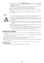
Страница 5: ...e mail and inform them you will formally notify them in writing through registered letter Packing list Ensure the packaging contains 1 LEDko T D Studio 1 Instruction manual 1 Main power plugs 2 General information 2 1 Safety informations Fire prevention 1 Never locate the fixture on any flammable surface 2 Minimum distance from flammable materials 0 5 m 3 Minimum distance from the closet illuminab...

Страница 6: ... is under warranty for 36 months from the purchase date against factory defec tions 2 Damage ought to unskillfulness inappropriate use or lack of suggested maintenance are excluded from the warranty 3 Warranty expires when the projector is opened by unauthorized personnel 4 Warranty doesn t include the replacement of the fixture 5 Serial number and model of the fixture are necessary to retrieve in...

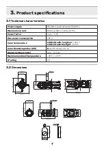
Страница 7: ...ithout optic 6 Kg 13 2 lbs Maximum ambient temperature 35 C 95 F IP rating 20 3 Product specifications 3 1 Technical characteristics 3 2 Dimensions 40 mm 1 5 in 212 mm 8 3 in 229 mm 9 0 in 188 mm 7 4 in 362 mm 14 2 in 194 mm 7 6 in 372 mm 14 6 in 275 mm 10 8 in 189 mm 7 4 in 198 8 mm 7 8 in 0 8 mm 0 03 in 180 mm 7 1 in 93 5 mm 3 7 in 7 5 m m 2 9 i n 212 mm 8 3 in 354 mm 13 9 in 355 mm 13 9 in 40 m...

Страница 8: ...components Components description A Adjustable yoke B Iris optional C Gobo holder optional D Lens adjusting handles E Yoke locking handle F Gel frame locking spring G Profile blade H Interchangeable optic A B C D F E G H ...

Страница 9: ...9 3 4 Back panel description Display Menu button Enter button PowerCon In PowerCon Out Plus button Minus button DMX In DMX Out ...

Страница 10: ...nto the body s receptacle and turn the optic 60 until it is firmly assembled to the projector body free to rotate but not free to detach itself from the body Ensure the optic to the body by tightening the two screws previously loosened 4 1 Optical installation Warning When the protective cap is removed never lean the fixture facing down The front lens can be seriously damaged ...

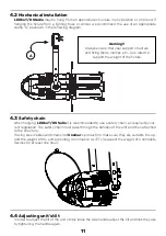
Страница 11: ...afety chain When hanging LEDko T D Studio it is recommended to use a safety chain as required by cur rent legislation The safety chain must pass through the handles of the unit and then attached to the structure If using steel cables and chains not Coemar s production make sure they are suitable to sup port the weight of the unit according to normative UL ETL required the weight of 6 complete devi...

Страница 12: ...tion to mains power LEDko T D Studio is equipped with two power connectors one as input and one as output which can be used to feed up to 8 at 230 V or 4 115 V fixtures The max absorption of LEDko T D Studio is reported in the following table 230 V 0 92 A constant during normal exercise 115 V 1 83 A constant during normal exercise 5 1 Operating voltage and frequency The unit may operates at voltag...

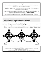
Страница 13: ...ld be carried out by a suitably qualified personnel Warning Make sure that screening and conductors are not in contact one another or with the metal housing of the connector Pin 1 and housing must never be connected to the power supply unit 6 1 Control signal connection by XLR5 plugs The digital control signal is transmitted to the projector via a two pole cable screened in accord ing to the Inter...

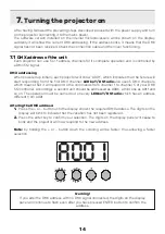
Страница 14: ...D Studio also uses 5 DMX channels which means that it will respond to the commands from channel 1 to channel 5 of your DMX 512 controller Accordingly a second unit should be addressed as A006 a third one as A011 and so on The operation must be carried out on every LEDko T D Studio which has an address different from A001 Altering the DMX address 1 Press the or button until the display shows the re...

Страница 15: ... stop strobe 208 209 82 82 proportional random strobe effect with variable speed from slow to fast 210 255 82 100 5 special functions step park no effect 0 9 0 4 600 Hz 10 84 4 33 fan at low noise speed 85 96 33 38 fan at auto silent speed 97 108 38 42 proportional fan speed control from minimum to maximum 109 120 43 47 step fan at maximum speed 121 133 47 52 enables the automatic display blackout...

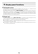
Страница 16: ...s of the projector so that it will respond differently to the controller therefore carefully read about the functions described here before carrying out any possible selection 9 2 Rapid count Through the display panel of LEDko T D Studio it is possible to quickly change the various numbers displayed for the different functions in the following 3 manners 1 Pressing the or buttons will cause the cou...

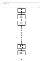
Страница 17: ...er menu 0 20 10 90 100 By pressing the enter button the user will enter the quick dimmer menu thanks to this menu it will be possible to increase and decrease the light intensity in steps of 10 in a range from 0 to 100 ...

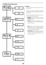
Страница 18: ...immer sets the luminous intensity Strobe manually sets the strobe DMX channel Store stores the modifications that will be set at the next times the fixture will be turned on Auto underthis setting the fan speed varies based on the overall tempera ture of the fixture to guarantee the maximum output possible Low noise this setting will keep the speed of the fan at the minimum level while the light o...

Страница 19: ...sh a button to unlock the keyboard it is necessary to hold any button down for a few seconds LED Frequency Allows to choose the operating frequen cy of the LEDs in order to avoid flickering issues with video recording devices The excursion varies from 611 Hz default to 19 000 Hz Reset It allows to restore the default factory settings of the unit Keeping pressed both ENTER and MENU allows to enter ...

Страница 20: ...perature Volt Shows the power supply voltage DMX Input Shows the value of the DMX channels received by the fixture on every channel that the fixture occupies on the line Rate Shows the refresh rate of the DMX signal sent by the console Alarm This menu shows the alarm statuses if there is any tEMP Temperature vOLt Supply Voltage dM In DMX Input rAtE DMX Rate ALrM Alarms brd Board Temperature t LEd ...

Страница 21: ... the overall hours of life of the fixture LED life shows the overall LED mod ule life LED life reset shows the overall LED module life currently installed Note this items can be reset in case of LED module replacement Software version Shows the software version currently in stalled in the fixture LEd LED Status FrE LED Frequency FAn Fan Voltage HOUr Usage Hours vErS Software Version UnIt Unit life...

Страница 22: ...hould be considered for the exclusive use of technicians and qualified personnel 9 6 Electronic alignment of the leds The display panel of LEDko T D Studio allows the electronic alignment of the LEDs this procedure is performed by Coemar at the time of testing this procedure may be useful for special effects or in case of replacement of internal components PCBs LEDs etc Altering the settings made ...

Страница 23: ... after 10 minutes of fixture inactivity Error code Description noal No Alarm No alarm The projector self diagnostic routine didn t find any issue DTER Data Error Data error Initial data loading has failed the projector loaded the default data settings restart the fixture again and if the error persists contact the Coemar assistance center ADER Address Error Address error The projector does not rec...

Страница 24: ...ns tube BC10011A015 Profile 50 lens tube BC10011A016 Profile 70 lens tube BC10011A024 Profile 90 lens tube BC10011A025 Profile Zoom 15 35 BC10011A017 Profile Zoom 25 50 BC10011A019 Profile Zoom 28 40 BC10011A003 Soft Profile Fresnel Zoom 14 40 BC10011A002 Soft Profile PC Zoom 11 38 BC10011A001 4 leaf barndoor ACO4202 Gobo frame holder BC10011A006 Iris BC10011A010 Donut 190 5 mm BC10011A028 Half To...

Страница 25: ...59 mm BC10011A032 Half Top Hat 159 mm BC10011A031 Top Hat 159 mm BC10011A033 Colour Frame Holder 159 mm BC10011A021 Gobo Slot Glass template holder 93 6 mm BC10011A030 Hook clamp 48 51 mm max load 20 Kg BC10011A047 Light clamp silver 48 51 mm max load 75 Kg BC10011A045 Light clamp black 48 51 mm max load 75 Kg BC10011A046 Clamp silver flat 13 30 mm ø 15 50 mm max load 20 Kg BC10011A043 Clamp black...

Страница 26: ... source of compressed air for removing dust For the cleaning of the housing use a soft cloth and a non aggressive cleaner Check that the internal fans and heat exchanger must be perfectly clean 11 3 Periodic controls Mechanical components Check the correct working of the mechanical parts and if needed replace them Make sure the projector is not mechanically damaged If necessary replace the worn pa...

Страница 27: ...ko T D Studio does not emit light Projector not powered on Make sure the power cord is plugged in or test the input voltage Wrong DMX address Check the DMX Address setting and the output signal of the controller LEDko T D Studio is not responding to DMX signal DMX signal may not reach LEDko T D Studio Inspect the cable connection correct poor connections or inefficient repair or replace damaged ca...

Страница 28: ...28 User notes ...

Страница 29: ...g center for waste electrical and electronic equipment The treatment and disposal of environmentally friendly helps prevent potential negative environmental and health and promote the reuse and or recycling of materials making upthe equipment Illegal disposal bythe userincludesthe application ofadministrative sanctions provided by law ...

Страница 30: ...ighting s r l Via Carpenedolo 90 46043 Castiglione delle Stiviere Mantova Italy phone 39 0376 1514412 fax 39 0376 1514380 info coemar com Coemar reserves the right to change specifications without prior notice ...

Отзывы: