Chapter 3: Connect the system
Connectors and pinout
37
3333
Co
nn
ec
t th
e
sy
st
em
3.5.2 SAILOR 6018 Message Terminal
3.5.2.1 Overview
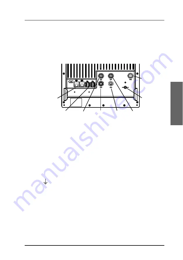
The drawing below shows the connector panel of the SAILOR 6018.
In the SAILOR 6110 system, the following connectors on the SAILOR 6018
are used:
• USB interface.
Connects to the SAILOR 1252 Printer and to the keyboard. You may also
connect a USB memory stick.
• LAN/ Ethernet interface.
Connects to the SAILOR 6197 Ethernet Switch.
•
ground stud.
Connects to ship ground.
• SYS (CAN) interface.
Connects to the SAILOR 3027 and optionally other equipment using
the CAN interface.
• DC Power input.
Connects to the SAILOR 6081 PSU and Charger.
The next sub-sections show the pin-out for these connectors.
The connectors OPT, ACC and AUX are not used in the SAILOR 6110. For a
2 x LAN/
Ethernet
4 x USB
Option
SYS
(CAN)
Auxiliary,
Speaker
and Alarm
Accessories,
Handset or Speaker
Microphones
Ground stud
Power and
Remote on
12 - 24 VDC
Содержание SAILOR 6110 mini-C GMDSS
Страница 1: ...SAILOR 6110 mini C GMDSS Installation manual ...
Страница 2: ......
Страница 30: ...Chapter 2 Install the system 18 Install the SAILOR 3027 Vertical pole Horizontal pole ...
Страница 100: ...Chapter 6 Service and maintenance 88 Available parts ...
Страница 112: ...98 154173 A www cobham com satcom ...


