


GR716-DS-UM, May 2019, Version 1.29
377
www.cobham.com/gaisler
GR716
stretching in order to support systems where master or physical layer limitations prevent stretching of
the I
2
C clock period.
37.2
Operation
37.2.1 Transmission protocol
The I
2
C-bus is a simple 2-wire serial multi-master bus with collision detection and arbitration. The
bus consists of a serial data line (SDA) and a serial clock line (SCL). The I
2
C standard defines three
transmission speeds; Standard (100 kb/s), Fast (400 kb/s) and High speed (3.4 Mb/s).
A transfer on the I
2
C-bus begins with a START condition. A START condition is defined as a high to
low transition of the SDA line while SCL is high. Transfers end with a STOP condition, defined as a
low to high transition of the SDA line while SCL is high. These conditions are always generated by a
master. The bus is considered to be busy after the START condition and is free after a certain amount
of time following a STOP condition. The bus free time required between a STOP and a START condi-
tion is defined in the I
2
C-bus specification and is dependent on the bus bit rate.
Figure 58 shows a data transfer taking place over the I
2
C-bus. The master first generates a START
condition and then transmits the 7-bit slave address. The bit following the slave address is the R/W bit
which determines the direction of the data transfer. In this case the R/W bit is zero indicating a write
operation. After the master has transmitted the address and the R/W bit it releases the SDA line. The
receiver pulls the SDA line low to acknowledge the transfer. If the receiver does not acknowledge the
transfer, the master may generate a STOP condition to abort the transfer or start a new transfer by gen-
erating a repeated START condition.
After the address has been acknowledged the master transmits the data byte. If the R/W bit had been
set to ‘1’ the master would have acted as a receiver during this phase of the transfer. After the data
byte has been transferred the receiver acknowledges the byte and the master generates a STOP condi-
tion to complete the transfer.
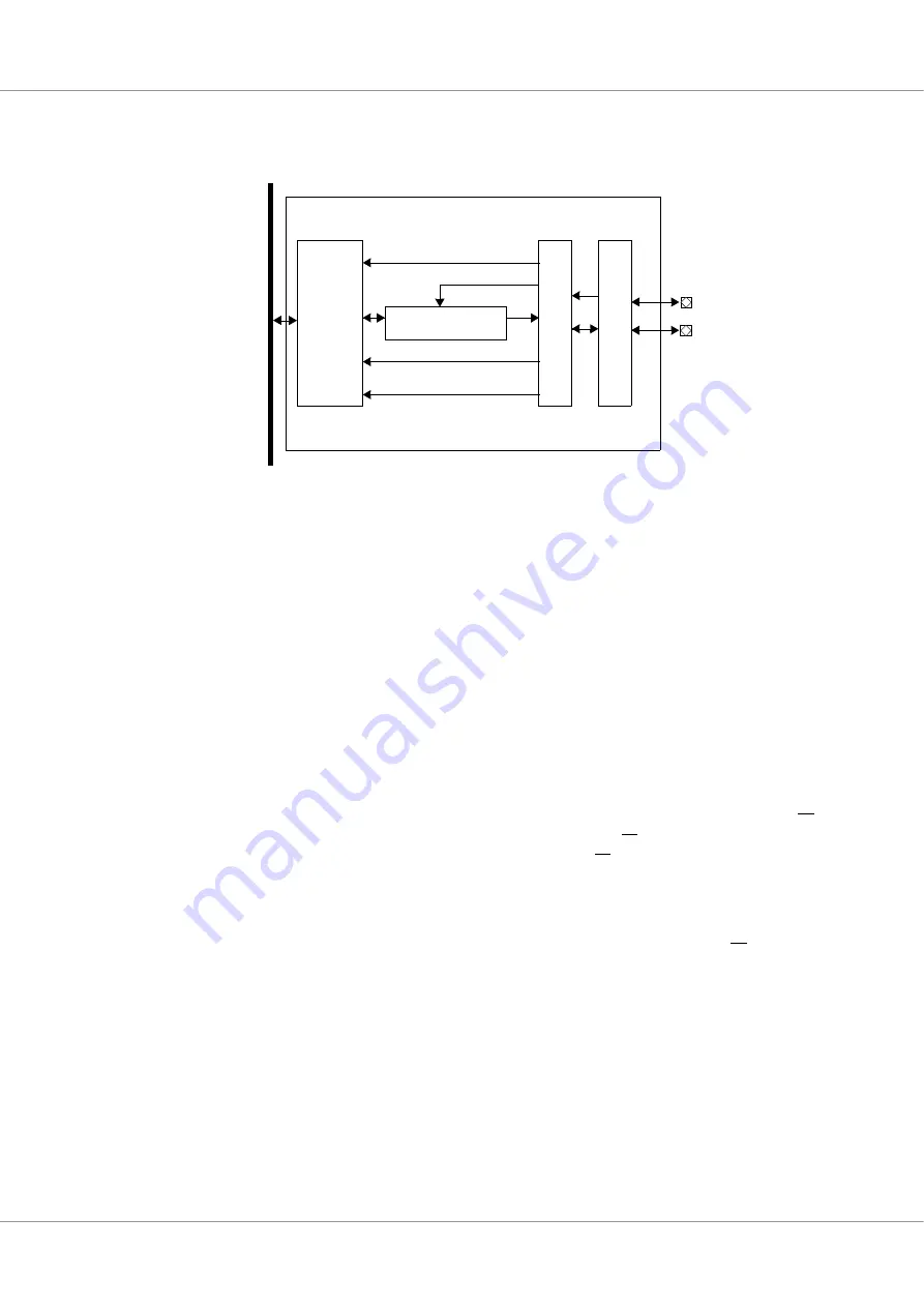
Figure 57.
Block diagram
A
M
B
A
A
H
B
Shift register
I2C2AHB
SCL
SDA
Control
FSM
START
STOP
SCL (filtered)
SDA (filtered)
S
ynchronizatio
n
Fi
lter