background image


Model SH-2012AH-QG   

Cutting Machine

C002


11 

3.6. Breakpoint Restoration Process


3.6.1.Breakpoint restoration 

1)


In case of manual pause or power outage in machining operation, the system will automatically save the 

current position of cutting torch as a breakpoint, which will be kept permanently in the system, whether 

power the system off or not.   

2)


In automatic mode, press [F2] key to select RESBREK function and then [START] key to start breakpoint 

restoration as long as there is no change with the current program.   

3)


If the position of cutting torch does not change, the system will prompt "Breakpoint" when a breakpoint is 

found  and  wait  for  subsequent  command.  User  may  select  piercing  directly  or  position  adjustment  of 

cutting torch. Refer to 3.4 for details.   

4)


If the position of cutting torch does change and is off from the breakpoint, the system will provide three 

options when a program breakpoint is found, which is virtually 

position adjustment of cutting torch

.   


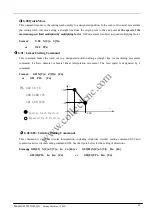
ORI PATH RET: 

To return to the breakpoint at speed G00, which is often used for the breakpoint set for cutting torch 

replacement;


CUT RET: 

little bit off from the breakpoint after breakpoint restoration, whic is somewhat like piercing along the exterior 

margin, making the breakpoint more smooth;


HOLE HERE: 

the same operation as previous, which can also be used for transitional cutting.   

Now, it is allowed to press a heavy-current function key such as IGN(ignition), PREHEA(piercing preheat), CUT(cutting 

oxygen), etc.   

Tip: The system will continue to process from the breakpoint location if [PIERCE] key is pressed after preheating.   

If press 

[ESC]

 key when a breakpoint is found, the system will exit machining mode.   

3.6.2Attention:   

Never  try  to  change  the  machining  program,  rotation  angle  and  scaling  proportion  whether  it  is 

breakpoint restoration or    power-off restoration, which will be automatically saved by the system and 

free from affect by power-off operation; otherwise, the system can not find the breakpoint.   

3.7.    SECTION(section selection) 

3.7.1. Start SECTION function 

SECTION: to assign system to start up machining operation from any section or piercing point.   

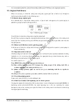
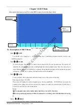
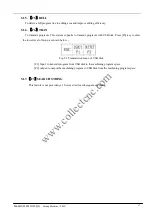
Press [F1] to select SECTION function and the system will show a menu as shown in the figure below:   

Fig.3.5 Dialog box of restart options after system pause and breakpoint restoration 

www.collectcnc.com

Содержание SH-2100AH-QG

Страница 1: ...AUTO MAN EDIT Command System SETUP LIBMINIT DIAGNOSE I O Interface Appendix 1 Pin definitions of height controller 2 SH 2012AH QG Software Upgrading Instructions 3 Installation Dimensional Diagrams 4...

Страница 2: ...sistency inspection to the contents of the printed file against the product described However we can t guarantee absolute accuracy due to the impossibility to eliminate inaccuracy completely Neverthel...

Страница 3: ...cceptance Please advise us timely in case of any debug in your use 12 Please contact the manufacturer in case of any problem Never disassemble assemble or modify the system the system without prior au...

Страница 4: ...ModeWindow 14 ChapterV EDITMode 16 5 1 Description of EDIT Menu 16 Chapter VI Command System 18 6 1 Description of Programing Symbols 18 6 2 CoordinateSystem 18 6 3 G BasicPreparatoryCommands 19 6 4 M...

Страница 5: ...0 Appendix I The Wiring Diagram and Pin Definitions for Model SH HC30 Height Controller Manufactured by Starfire 42 Appendix II Instructions for Software Upgrading Operation of SH 2012AH 44 Appendix I...

Страница 6: ...Ready for transitional cutting operation at any moment Special short line machining feature based on smooth travel extensively applicable to metal blanking as well as advertisement and ironwork fabri...

Страница 7: ...Model SH 2012AH QG Cutting Machine C002 2 1 3Starfire also supplies the following auxiliary products for compact CNC cutting machine w w w c o l l e c t c n c c o m...

Страница 8: ...hebottomleftcornerforyourinformation F1 AUTO Programmedcontrolofautomatic machining F2 MAN Tomanuallycontrolthepositionofcuttingnozzle F3 Edit Toedit modify input outputthemachiningprogram F4 SETUP To...

Страница 9: ...thefigurebelow Flamemode Fig 3 1AutomaticFunction AUTO Window Plasma Mode Active speed multiplying factor Program name Heavy current control output Piercing Hole No Kerf Input output indication Functi...

Страница 10: ...ning pause limitalarmsandtimedelay 3 1 4 Input and output Below the heavy current switches there are 3 rows 8 indicators The top indicators show the status of 13 input ports indicating no signal input...

Страница 11: ...ic mode and manual mode to adjust the speed multiplying factor 3 2 Function selection inAUTO mode It is allowed to invoke a machining program by means of EDIT feature If a program has been invoked as...

Страница 12: ...as follows 1 Determine the datum line Take one borderline of steel plate as baseline and move the cutting torch to the origin point of this baseline Press F2 to set the beginning point of measurement...

Страница 13: ...to starting automatic mode Select correct machining program and appropriate machining speed multiplying factor Move the cutting torch to the cutting position The cutting torch will be lifted automatic...

Страница 14: ...nt restoration If operator intends to change the position of cutting torch in the above mentioned states it is allowed to press and or key to do so in this case it is manual multiplying factor adjusta...

Страница 15: ...d After the cutting torch returns to the designated position it is allowed to select position adjustment of cutting torch refer to 3 4 or piercing directly by pressing the appropriate heavy current fu...

Страница 16: ...used for the breakpoint set for cutting torch replacement CUT RET little bit off from the breakpoint after breakpoint restoration whic is somewhat like piercing along the exterior margin makingthebre...

Страница 17: ...onagain b If it is the expected piercing point use heavy current control switch for ignition and preheat before press PIERCE key to start operation c If REFPOSITION option Reference Point Positioning...

Страница 18: ...ally Thesystemispreheated 2 Press START key at the end of preheat The cutting torch will reach the piercing point along a straight line at selected cutting speed and then go on machining 3 8 3NO HOLE...

Страница 19: ...play in manual mode is the same as it in automatic mode except that the multiplying factor is manually adjustable which affects manual operation return speed to reference point move speed etc There ar...

Страница 20: ...E INCREMENT 0050 000 previous input value by default In MOVE mode if direction key is pressed once the cutting torch will move an increment at the speed of the current maximum speed limit multiplied b...

Страница 21: ...rogram editing area if ESC key is pressed the load function will be abandoned 5 1 3 F3 SAVE To save program After a program is edited and ready to save the system will prompt Enter program name 1234 T...

Страница 22: ...rams with USB disk Press F6 key to enter the lower level of menu as shown below F1 Input to transmit program from USB disk to the machining program space F2 output to output the machining program to U...

Страница 23: ...center and X axis original value in arc cutting operation J The difference between the coordinate value of circle center and Y axis original value in arc cutting operation R To designate arc radius H...

Страница 24: ...X Y and U V all represent the values relative to the current point Format G90 Format G91 Exemple 1 G92 X0 Y0 G91 Relative coordinate system G00 X100 Y100 Quickly reach point 100 100 equivalent to G00...

Страница 25: ...d position along a straight line As machining movement command it allows uniaxial or biaxial linear interpolation movement The feed speed is designated by F command Format G01 X U n Z W n Fn or G01 PP...

Страница 26: ...nt program will be executed continually If Exit key is pressed the execution of the current program will be aborted 8 G26 G27 G28 Return Reference Point Commands Thess commands make the cutting torch...

Страница 27: ...tter Radius Compensation Commands Format G41 or G42 Rn Program segment to be compensated G40 Notes G41 is to compensate a half diameter of flame leftwardsalong the machining path G42 is to compensate...

Страница 28: ...time is insufficient it will be prolonged to 150 seconds automatically by pressing PAUSE key If preheating is done in the midway press START key to abort the time delay The new preheating time will be...

Страница 29: ...r in value Because of gravity the lowering action is faster than lifting action Operation sequence turn on the torch lowering switch M16 count the time delay of lowering torch refer to 7 3 for flame p...

Страница 30: ...preheating delay torch lifting lowering delay lifting lowering of piercing torch piercing delay etc Plasma parameters Torch positioning delay M commands for arc ignition M commands for arc breaking ar...

Страница 31: ...imumspeedlimit inseconds Uniformaccelerationtime Intheprocessofacceleration deceleration thetimeneededforlinearacceleration whichisusually littlebitsmallerthantheadjustmenttimebyonetenthapproximately...

Страница 32: ...s0 008mm itsnumerator denominatorratioofelectronicgear 8 1 ElectronicGearRatio PitchofScrewRod 1000 360 SubdivisionNumber SteppingAngle DriveRatio Thecomputationmethod adjustmentmethod ofelectronicgea...

Страница 33: ...The system will give an alarm when program coordinate exceeds the set soft positive negativelimit Ifitwillnotbeused theparametershouldbesethigherthanactualvaluesinmmorinch 7 3 Flame Cutting Parameter...

Страница 34: ...d Arc voltage test option It is used to determine if arc voltage is tested or not in plasma cutting operation To enable arc voltage test take 1 for the option User should test arc voltage feedback at...

Страница 35: ...ttern in advance without pattern pretreatment see the parameters below The systemwillmachinetheworkpiecewhendrawingthepattern X axis width of steel plate The actual width of steel plate along X axis w...

Страница 36: ...nFig 7 7 Fig 7 7 Height control function Arc voltage height control option This option is editable only when plasma arc voltage control is used along with the height controller manufactured by Starfir...

Страница 37: ...ons for parametersasmuchaspossible 2 When the parameters are entered the control system will drawn the pattern based on the entered parameters which is very helpfultographiccheck Inthesystemmainmenu p...

Страница 38: ...te The system will prompt to input rotation angle and press ENTER or F6 to acknowledge The pattern rotated such an angle will appear Counterclockwise direction is taken as positive angle F4 Layout The...

Страница 39: ...NC which should have the following structure G92 X0 Y0 User defined module Note The original program should not have more than 59 lines G28 The last line should command the torch to return to the ref...

Страница 40: ...ove cursor to any position of the 8 optical isolation output ports and change the level state of output with 0 and 1 1 stands for enable while 0 stands for disable Refer to Definitions of Input output...

Страница 41: ...to normally opened contact NO contact or normally closed contact NC contact After powered on the system will automatically check the level of activation bit as control reference Therefore if external...

Страница 42: ...operation 5 NO contact output of height control corner signal relay auto manual switch for height control 18 NO contact output of arc ignition signal relay 6 Common port for COM OH1 OH2 OH3 OH4 isolat...

Страница 43: ...7 15 8 1 9 2 10 3 11 4 12 5 13 6 14 7 15 8 XDIR XCP YDIR YCP X YDIR X YCP OPTO 5V common 5V Relay Relay Relay Relay 24V 24G COM 01 02 COM Input output Motor DC24V KR KQ Cutting oxygen solenoid valve...

Страница 44: ...ng operation of cutting torch with height controller NO contact Output for lifting operation of cutting torch with height controller NO contact Auto manual switch for output M38 height controller in f...

Страница 45: ...e not necessary to connect 4 K1 is flame plasma selective relay M20 10 8 Pin Definitions 1 The pin definitions of 15 pin connector for Model SH HC30 height controller manufactured by Starfire are as f...

Страница 46: ...transmission 3 RXD RS232 receive 8 24G Ground for 24V power supply 9 I8 Input Port 9 for External Control Box X 10 I9 Input Port 10 for External Control Box X 11 I10 Input Port 11 for External Control...

Страница 47: ...s List of 9 Pin Connector for Divider Board No Attribute Description 2 Power supply Ground of 24V power supply for height controller 5 Power supply Ground of 24V power supply for height controller 6 O...

Страница 48: ...eight Controller 4 Wiring Diagram of Capacitance type Height Controller 15 pin connector for height controller 25 pin connector for CNC system 9 pin connector of divider board 15 15 pin connector for...

Страница 49: ...If program upgrading fails the system will prompt Upgrade Failure and sound continuous beeps 4 New program startup Power the system off and unplug the USB disk Reboot the system to start up the upgra...

Страница 50: ...Model SH 2012AH QG Cutting Machine C002 45 Appendix III Installation Dimensional Drawing w w w c o l l e c t c n c c o m...

Страница 51: ...ting oxygen is giv en arc extinction Motor fails to run Check the system wiring Loose connection or disco nnection Secure the connection Check the driver Check for any alarm mess age or if the setting...

Страница 52: ...u t and output Check if they are well co nnected Secure the connection Check if 24V power supp ly is normal or not Check the voltage of 25 pi n port between Pin 24 an d Pin 25 Check the switching powe...

Страница 53: ...tem input output and the exposed part at the ca ble end must not be longer than 30mm c The unused input end must be connected to 24V ground wire d A 0 01uF capacitor should be used between the 24V gro...

Страница 54: ...22 Notes 1 The start key pause key emergency stop key and backspace key are required to connect to the input output port through normally closed contacts These four keys are enabled at system booting...

Страница 55: ...w w w c o l l e c t c n c c o m...

Отзывы: