STEERING AND FRONT SUSPENSION
Steering Column
7
1. Step 1
2. Step 2
3. Step 3
1. Step 1
2. Step 2
3. Step 3
1500-18200-10255
Figure 7-4
Steering Shaft – Bottom End
1500-18200-10256
Figure 7-5
Steering Shaft – Top End
STEERING COLUMN INSTALLATION
1.
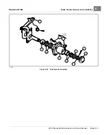
Install boot (12). Reinstall mount (4 and 5) onto the end of the steering column. Tighten bolts (6) to 20 ft·lb (27
N·m)
.
2.
For ease of assembly and to prevent corrosion, apply a light coat of anti-seize or lubricating compound to
both splined ends of the steering shaft.
3.
Position the steering column assembly in the vehicle while inserting the steering column shaft into the upper
universal joint (1). The flat portion of the steering shaft spline (19) must be aligned with the bolt hole in the
universal joint (1) before sliding the spline into the universal joint. While holding the steering column in place,
attach it to the frame using bolts (8), washers (7), and nuts (9)
. Thread the nuts onto the
bolts but do not tighten them.
4.
Install wide washer (35), washer (11) and screw (10). Tighten to 20 ft·lb (27 N·m)
.
5.
Install the bolt (2) and lock washer (3) on the upper universal joint and finger-tighten.
6.
Tighten the two nuts (9) and bolts (8) to 18 ft·lb (24.4 N·m)
7.
Tighten the bolt (2) on the upper universal joint to 15 ft·lb (20 N·m)
.
8.
Check the other two bolts of the universal joint (1) to ensure that they are properly tightened to 15 ft·lb (20
N·m)
.
9.
Install cowl.
See Cowl Installation, Section 4, Page 4-4.
10.
Install the steering wheel.
See Steering Wheel Installation on page 7-2.
2019 Transporter Maintenance and Service Manual
Page 7-5
Содержание TransPorter 4
Страница 2: ......
Страница 18: ...Pagination Page 1 General Warnings SAFETY Page 1 6 2019 Transporter Maintenance and Service Manual ...
Страница 112: ...8 Tires WHEELS AND TIRES Figure 8 2 Inflate Tire Page 8 4 2019 Transporter Maintenance and Service Manual ...
Страница 271: ...ELECTRIC MAIN HARNESS Wiring Diagrams Electric Main Harness 18 ...
Страница 272: ... Page intentionally left blank ...
Страница 273: ...ELECTRIC INSTRUMENT PANEL HARNESS Wiring Diagrams Electric Instrument Panel Harness 18 ...
Страница 274: ... Page intentionally left blank ...
Страница 275: ...ELECTRIC ACCESSORIES HARNESS Wiring Diagrams Electric Accessories Harness 18 ...
Страница 276: ... Page intentionally left blank ...
Страница 282: ...NOTES ...
Страница 283: ...NOTES ...
Страница 284: ...NOTES ...
Страница 285: ......
Страница 286: ......


