


12
Test Procedures
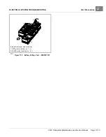
ELECTRICAL SYSTEM TROUBLESHOOTING
6.
If there is 48 volts, do the following:
7.
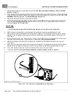
Make sure that the green and tan wires are securely connected to the circuit breaker.
8.
Make sure that the 24 pin connector has no corrosion.
9.
Make sure that the 24 pin connector is securely connected to the controller.
10.
Make sure that the number 3 pin of the 24 pin connector is seated correctly into the 24 pin connector.
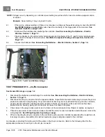
11.
Number 3 pin voltage check:
11.1.
Set the Run/Tow switch to TOW.
11.2.
Disconnect the batteries.
11.3.
Disconnect the 24 pin connector from the controller.
11.4.
Connect the batteries. Do not connect the 24 pin connector to the controller.
11.5.
Set the Run/Tow switch to RUN.
11.6.
Check the voltage at the number 3 pin of the 24 pin connector.
12.
If there is voltage at the number 3 pin:
12.1.
Replace the controller.
NOTE:
Make sure the correct controller is used.
Early 2006 model year to 2013 model year (with onboard computer) and Villager 6 & 8: use controller model
number 1520
Mid model year 2014 models without onboard computer (OBC) onboard charger (Delta Quiq): use controller
model number 1520L
13.
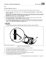
If there is no voltage at the number 3 pin:
13.1.
Check for voltage at the green wire on the circuit breaker switch.
13.1.1.
If there is 48 volts, there is a broken wire between the tan wire on the circuit breaker and the number
3 pin on the 24 pin connector. Use the wiring diagram to find the broken wire.
14.
Set the Run/Tow switch to TOW.
15.
Disconnect the batteries.
16.
Connect the 24 pin connector to the controller.
17.
Connect the batteries.
18.
Set the Run/Tow switch to RUN.
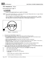
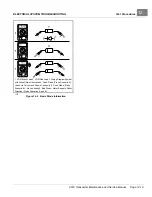
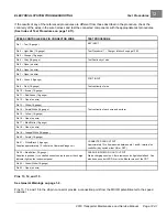
TEST PROCEDURE 6 – Wire Harness Diodes
See General Warnings on page 1-2.
A diode is designed to conduct current in one direction only. Depending on the application, diodes are used in the
vehicle to control electrical system logic, or to help protect relay and switch contacts from excessive arcing.
See
following NOTE.
NOTE:
If a diode conducts current in both directions, the diode has failed closed. If a diode will not conduct current in
either direction, the diode has failed open
Page 12-18
2019 Transporter Maintenance and Service Manual
Содержание TransPorter 4
Страница 2: ......
Страница 18: ...Pagination Page 1 General Warnings SAFETY Page 1 6 2019 Transporter Maintenance and Service Manual ...
Страница 112: ...8 Tires WHEELS AND TIRES Figure 8 2 Inflate Tire Page 8 4 2019 Transporter Maintenance and Service Manual ...
Страница 271: ...ELECTRIC MAIN HARNESS Wiring Diagrams Electric Main Harness 18 ...
Страница 272: ... Page intentionally left blank ...
Страница 273: ...ELECTRIC INSTRUMENT PANEL HARNESS Wiring Diagrams Electric Instrument Panel Harness 18 ...
Страница 274: ... Page intentionally left blank ...
Страница 275: ...ELECTRIC ACCESSORIES HARNESS Wiring Diagrams Electric Accessories Harness 18 ...
Страница 276: ... Page intentionally left blank ...
Страница 282: ...NOTES ...
Страница 283: ...NOTES ...
Страница 284: ...NOTES ...
Страница 285: ......
Страница 286: ......