


12
Test Procedures
ELECTRICAL SYSTEM TROUBLESHOOTING
11 – Charger Interlock
12 – MCOR Voltage
13 – Motor Speed Sensor
14 – A1 and A2 Motor Voltage
15 – 24-Pin Connector
16 – Reverse Buzzer
17 – Walk Away Braking Relay
18 – Charge Indicator Light
19 – 4-Pin Connector (for Connected Car Device)
20 – Emergency Stop Switch
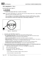
TEST PROCEDURE 1 – Batteries / Voltage Check (BPV)
See General Warnings on page 1-2.
NOTE:
This is a voltage test.
If battery voltage drops below 34 volts during operation, the vehicle will shut down and give a Low Battery
Voltage/Undervoltage fault.
The batteries must be properly maintained and fully charged in order to perform the following test procedures.
Battery maintenance procedures, including watering information and allowable mineral content, can be found
in the Battery section of this manual.
See Battery Care on page 14-6.
The battery voltage can be displayed with the CDT handset. If an CDT handset is not available, proceed to
Batteries /
Voltage Check without the CDT Handset
.
Batteries / Voltage Check with the CDT Handset
1.
Connect the CDT to the vehicle.
2.
Access the Monitor menu and select BATT VOLTAGE by using the SCROLL DISPLAY buttons. The CDT should
indicate at least 48 volts.
See following NOTE.
If not, check for loose battery connections or a battery installed in
reverse polarity.
Refer to Batteries on page 14-1 for further details on battery testing.
NOTE:
The voltage displayed through the CDT shows what the controller thinks it sees. If the controller is not
operating properly, it may display a different voltage from what the battery pack voltage (BPV) really is. Always
compare and confirm with readings obtained using a multimeter in the following procedure.
Batteries / Voltage Check without the CDT Handset
1.
If necessary, see Testing Basics on page 12-11.
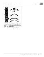
2.
With batteries connected and using a multimeter set to 200 volts DC, place red (+) probe on the positive (+) post
of battery no. 1 and the black (–) probe on the negative (–) post of battery no. 6
.
3.
The multimeter should indicate at least 48 volts. If not, check for loose battery connections or a battery installed in
reverse polarity.
Refer to Batteries on page 14-1 for further details on battery testing.
Page 12-12
2019 Transporter Maintenance and Service Manual
Содержание TransPorter 4
Страница 2: ......
Страница 18: ...Pagination Page 1 General Warnings SAFETY Page 1 6 2019 Transporter Maintenance and Service Manual ...
Страница 112: ...8 Tires WHEELS AND TIRES Figure 8 2 Inflate Tire Page 8 4 2019 Transporter Maintenance and Service Manual ...
Страница 271: ...ELECTRIC MAIN HARNESS Wiring Diagrams Electric Main Harness 18 ...
Страница 272: ... Page intentionally left blank ...
Страница 273: ...ELECTRIC INSTRUMENT PANEL HARNESS Wiring Diagrams Electric Instrument Panel Harness 18 ...
Страница 274: ... Page intentionally left blank ...
Страница 275: ...ELECTRIC ACCESSORIES HARNESS Wiring Diagrams Electric Accessories Harness 18 ...
Страница 276: ... Page intentionally left blank ...
Страница 282: ...NOTES ...
Страница 283: ...NOTES ...
Страница 284: ...NOTES ...
Страница 285: ......
Страница 286: ......