UNITIZED TRANSAXLE
Unitized Transaxle Removal
2001 Pioneer 900 Gasoline Vehicle Maintenance and Service Manual Page 16-7
16
∆ CAUTION
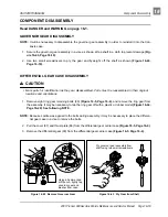
• If the bearing was removed from the shaft, replace it with a new one.
• Do not tighten the bearing puller wedge attachment against the axle shaft. This could damage the
axle shaft when the bearing and collar are pressed on.
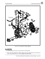
AXLE SHAFT INSTALLATION
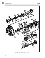
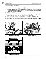
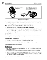
1. Clean bearing and seal seats in axle tube (75 or 76) (Figure 16-5, Page 16-4).
2. Place a new seal (72) (Figure 16-5, Page 16-4) in axle tube with seal lip facing inside of the axle tube.
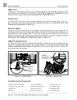
Use an axle seal tool (CCI 1014162) to press it in until it seats firmly in position (Figure 16-8, Page 16-
6). See following NOTE.
NOTE: The new seal can be installed by tapping the axle seal tool with a mallet.
3. Clean the axle shaft and splines and then insert the shaft, splined end first, through the seal and into
the axle tube. Be careful not to damage the seal. Then advance the shaft through the inner bearing and
rotate it to align the shaft splines with the splined bore of the differential side gear. Continue advancing
the shaft until the bearing seats against the axle tube shoulder.
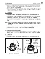
4. Install the retaining ring (70) (Figure 16-5, Page 16-4) in the axle tube. See also Figure 16-3, Page 16-3.
5. Place a 1/4 to 3/8 inch (6-10 mm) diameter rod against the retaining ring and tap lightly at four to five
locations to ensure it is properly seated. See following WARNING.
∆ WARNING
• Be sure retaining ring is properly seated in its groove. If ring is not properly installed, the axle
assembly will separate from the transaxle and damage the axle assembly and other
components. Loss of vehicle control could result in severe personal injury or death.
UNITIZED TRANSAXLE REMOVAL
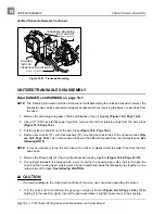
Read DANGER and WARNING on page 16-1.
1. Disconnect the battery cables, negative cable (–) first.
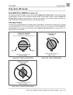
2. Close the fuel shut-off valve on fuel tank. See Figure 14-20, Section 14, Page 14-27.
3. Detach all wires, hoses, etc. connecting the powertrain to the vehicle.
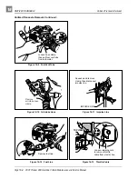
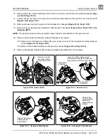
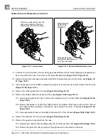
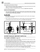
3.1. Disconnect the carburetor vent tube from the carburetor (Figure 16-9, Page 16-8).
3.2. Disconnect the air intake hose from the carburetor (Figure 16-10, Page 16-8).
3.3. Disconnect impulse line from fuel pump (Figure 16-11, Page 16-8).
3.4. Loosen the hose clamp and then disconnect the fuel line from the carburetor. To prevent spilling
fuel, the disconnected end of the line can be pushed onto the impulse line fitting of the fuel pump
(Figure 16-12, Page 16-8).
3.5. Remove the cover from the electrical component box. Then loosen the hardware securing the
accelerator cable to the box. Disconnect the cable from the actuator cam and remove it from the
box (Figure 16-13, Page 16-8).
Содержание Pioneer 900
Страница 1: ......
Страница 2: ......
Страница 22: ...3...
Страница 88: ...7...
Страница 92: ...8...
Страница 100: ...9...
Страница 108: ...10...
Страница 188: ...12...
Страница 268: ...14...
Страница 272: ...15...
Страница 316: ...16...
Страница 332: ...17...
Страница 341: ......
Страница 342: ......
Страница 343: ......


