11
Test Procedures
IQ SYSTEM TROUBLESHOOTING
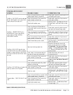
A procedure is provided for testing each of the wires in the 16-pin connector. Refer to the following chart for the
appropriate procedure for each pin in the 16-pin connector.
If the results of any of the referenced procedures are different from those described in the procedure, check the
continuity of the wires in the wire harness and test the connected components with the appropriate test procedures.
See Index of Test Procedures.
SPEED CONTROLLER 16-PIN
CONNECTOR WIRE
FUNCTION
TEST PROCEDURE
Pin 1 – White (18-gauge)
To high side of throttle position sensor
Pin 2 – Yellow (18-gauge)
Pedal position signal from throttle
position sensor
Test Procedure 10 – Pins 1, 2, and 13 on page
11-22
Pin 3 – Open (No wire)
Pin 4 – Open (No wire)
Pin 5 – Light Blue (18-gauge)
OBC
Test Procedure 11 – Pin 5 on page 11-22
Pin 6 – Green (18-gauge)
To throttle position sensor limit switch
for accelerator pedal input
Test Procedure 12 – Pin 6 on page 11-24
Pin 7 – Orange/White (18-gauge)
To low side of reverse buzzer
Test Procedure 13 – Pin 7 on page 11-24
Pin 8 – Brown (18-gauge)
Forward signal from FNR
Test Procedure 14 – Pins 8 and 16 on page
11-25
Pin 9 – Gray (18-gauge)
To Tow switch sonic weld
Test Procedure 15 – Pin 9 on page 11-26
Pin 10 – Tan (18-gauge)
To key switch sonic weld
Test Procedure 16 – Pin 10 on page 11-27
Pin 11 – Open (no wire)
Pin 12 – Blue/White (18-gauge)
To low side of solenoid coil
Test Procedure 17 – Pin 12 on page 11-28
Pin 13 – Black/White (18-gauge)
Negative (-) side of motor speed sensor
and throttle position sensor
Test continuity of wire and perform Test
Procedure 10 – Pins 1, 2, and 13 on page
11-22 and Test Procedure 21 – Motor Speed
Sensor on page 11-31
Pin 14 – Light Green (18-gauge)
To motor speed sensor output
Pin 15 – Red (18-gauge)
Positive (+) side of motor speed sensor
Test continuity of each wire and perform Test
Procedure 21 – Motor Speed Sensor on page
11-31
Pin 16 – Blue (18-gauge)
Reverse signal from FNR
Test Procedure 14 – Pins 8 and 16 on page
11-25
TEST PROCEDURE 10 – Pins 1, 2, and 13
See General Warnings on page 1-1.
Pins 1, 2, and 13 in the 16-pin connector provide a connection point from the throttle position sensor to the speed
controller. Two wires simply supply 4.65 volts to the sensor. The sensor varies the voltage according to pedal position
and sends that voltage signal to the controller through the third wire. See chart above. To test these wires,
see Test
Procedure 4 – Throttle Position Sensor Voltage on page 11-16
.
TEST PROCEDURE 11 – Pin 5
See General Warnings on page 1-1.
Pin 5 in the 16-pin connector provides a connection point for the solenoid lockout circuit from the onboard computer to
the speed controller.
Page 11-22
2009 Electric Precedent Maintenance and Service Manual
Содержание 2009 Precedent
Страница 2: ......
Страница 4: ......
Страница 16: ......
Страница 22: ......
Страница 48: ......
Страница 64: ......
Страница 136: ......
Страница 174: ......
Страница 196: ......
Страница 218: ......
Страница 262: ......
Страница 264: ......
Страница 306: ......
Страница 307: ......
Страница 308: ......
Страница 310: ......
Страница 311: ......
Страница 312: ......


