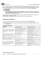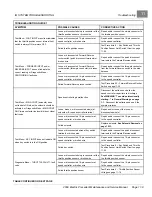
11
Test Procedures
IQ SYSTEM TROUBLESHOOTING
21 – Motor Speed Sensor
22 – Solenoid Continuity
23 – Forward/Reverse Rocker Switch
24 – Reverse Buzzer
25 – Rebooting the Onboard Computer
26 – Battery Warning Light
TEST PROCEDURE 1 – Batteries / Voltage Check
See General Warnings on page 1-1.
NOTE:
The batteries must be properly maintained and fully charged in order to perform the following test procedures.
Battery maintenance procedures, including watering information and allowable mineral content, can be found
in
Section 16 — Batteries
of this manual.
See Battery Care, Section 16, Page 16-16.
The battery voltage can be displayed with the IQDM handset. If an IQDM handset is not available, proceed to
Batteries / Voltage Check without the IQDM Handset
.
Batteries / Voltage Check with the IQDM Handset
1.
Connect the IQDM to the vehicle.
See Plugging the Handset into the Vehicle, Section 13, Page 13-1.
2.
Access the Test menu and select BATT VOLTAGE by using the SCROLL DISPLAY buttons. The IQDM should
indicate at least 48 volts with the batteries fully charged. If not, check for loose battery connections or a battery
installed in reverse polarity.
Refer to Section 16 — Batteries for further details on battery testing.
Batteries / Voltage Check without the IQDM Handset
1.
With batteries connected and using a multimeter set to 200 volts DC, place red (+) probe on the positive (+) post
of battery no. 1 and the black (–) probe on the negative (–) post of battery no. 4
(Figure 11-6, Page 11-14)
or
battery no. 6
(Figure 11-7, Page 11-14)
. The multimeter should indicate at least 48 volts with the batteries fully
charged. If not, check for loose battery connections or a battery installed in reverse polarity. Refer to Section
16 — Batteries for further details on battery testing.
POS
NEG
POS
NEG
2
4
1
3
POS
POS
NEG
NEG
2m
20
m
200
m
2k
200
200
200
200
20
2
200
m
500
20k
200k
2000
k
1000
OFF
WAVETEK
5XL
V
V
V
A
!
!
COM
200nA
MAX
1000 ---
750V
FUSED
(Viewed from driver side of vehicle)
1. RED probe to battery no. 1 (+).
2. BLACK probe to battery no. 4 (-).
2
3
4
5
6
+
1
2m
20
m
200
m
2k
200
200
200
200
20
2
200
m
500
20k
200k
2000
k
1000
OFF
WAVETEK
5XL
V
V
V
A
!
!
COM
200nA
MAX
1000 ---
750V
FUSED
(Viewed from driver side of vehicle)
1. RED probe to battery no. 1 (+).
2. BLACK probe to battery no. 6 (-).
Figure 11-6
Battery Voltage Test – 4 x 12 Volt Battery
Configuration
Figure 11-7
Battery Voltage Test – 6 x 8 Volt Battery
Configuration
Page 11-14
2009 Electric Precedent Maintenance and Service Manual
Содержание 2009 Precedent
Страница 2: ......
Страница 4: ......
Страница 16: ......
Страница 22: ......
Страница 48: ......
Страница 64: ......
Страница 136: ......
Страница 174: ......
Страница 196: ......
Страница 218: ......
Страница 262: ......
Страница 264: ......
Страница 306: ......
Страница 307: ......
Страница 308: ......
Страница 310: ......
Страница 311: ......
Страница 312: ......


