background image

5

5

4

4

3

3

2

2

1

1

D

D

C

C

B

B

A

A

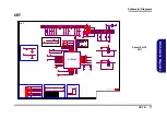
CRT

POWER

I2C Control Debug Port
connect to EC/PCH

Ra

Rb

Ra R1496 pull up  VCCKV12 from LDO enable
Rb R1497 pull down VCCKV12 from external

Power On Configuration

DP Signals from GPU

RTD2168 Slave Address
0x64 / 0x65 and 0x68 / 0x69

Rc

Rc
Rc

Rd

Re

Rf

Rom only mode

ep mode

EEPROM MODE

POL1_SDA

POL2_SDC

Rc

Rf

Rd

Re

Rd

Rf

 H

 H

 H

L

L

L

A_VCC33

VDD_DAC_33

CSDA

CSCL

POL1_SDA

AUX_CH_N

DAC_RED

DAC_GREEN

AUX_CH_P

LANE1_P

LANE1_N

LANE0_P

LANE0_N

VGA_HPD

DAC_BLUE

VDD_DAC_33

VCCKV1

2

3.

3V

S

VG

A_

HS

VG

A_

VS

VG

A_

SDA

1.2V_LDO_EN

POL1_SDA

POL2_SDC

3.

3V

S

VG

A_

SCL

CSDA

CSCL

A_VCC33

VGA_HPD

EPAD_GND

LANE1_N

LANE1_P

LANE0_P

LANE0_N

RRX

AUX_CH_P

AUX_CH_N

VCCKV12

XTL

I

1.2V_LDO_EN

VCCKV12

POL2_SDC

DAC_GREEN

DAC_RED

FGRN

FBLUE

FRED

DAC_BLUE

VGA_SDA

VGA_SCL

VGA_HS_R

VGA_VS_R

VGA_HSYNC

VGA_VSYNC

VGA_HS_R

VGA_HS

VGA_VS

VGA_VS_R

XTL

O

3.3VS

3.3VS

3.3VS

3.3VS

3.3VS

1.2V_VGA

3.3VS

5VS_CRT

5VS_CRT

5VS

5VS_CRT

5VS

7,15,19,21,24..26

3.3VS

2,4..8,13..15,17..26,28,32

V_VCCDDQ

2,9,13,14,28

VGA_AUX_CH_N

2

VGA_AUX_CH_P

2

VGA_LANE0P

2

VGA_LANE0N

2

VGA_LANE1P

2

VGA_LANE1N

2

VGA_HPD

2

Title

Size

Document Number

Rev

Date:

Sheet

of

1.0

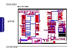
[16] VGA_RTD2168

Custom

16

38

W ednesday, August 24, 2016

ᙔ!Ϻ!ႝ!တ!!DMFWP!DP/

6-7P-W 94J3-003

6-71-W94J0-D02B

Title

Size

Document Number

Rev

Date:

Sheet

of

1.0

[16] VGA_RTD2168

Custom

16

38

W ednesday, August 24, 2016

ᙔ!Ϻ!ႝ!တ!!DMFWP!DP/

6-7P-W 94J3-003

6-71-W94J0-D02B

Title

Size

Document Number

Rev

Date:

Sheet

of

1.0

[16] VGA_RTD2168

Custom

16

38

W ednesday, August 24, 2016

ᙔ!Ϻ!ႝ!တ!!DMFWP!DP/

6-7P-W 94J3-003

6-71-W94J0-D02B

R1506

*0_04

R428

75_1%

_04

C532

0.1u_10V_X5R_04

U105

*U74LVC1G125G-AL5-R

1

2

5

4

3

C1467

2.2u_6.3V_X5R_04

R1497

*4.7K_04

C525

10p_50V

_N
P

O

_04

C480

0.1u_10V_X5R_04

L39

FCM1005MF-600T01

C246

*1u_6.3V_X5R_04

X8

*FSX3M_27MHz

1

2

3

4

C526

1000p_50V

_X
7R
_04

R1508

0_04

R1522
*10mil_04

C281

*1u_6.3V_X5R_04

R408

*4.7K_04

C1468

10u_6.3V_X5R_06

C324

15p_50V

_N
P

O

_04

R310

2.2K_04

R1502

*4.7K_04

R390

100K_04

C420

15p_50V

_N
P

O

_04

C1466

0.1u_16V_Y5V_04

R1507

0_04

C528

10p_50V

_N
P

O

_04

L46

FCM1005MF-600T01

C522

*18p_50V_NPO_04

L77

FCM1005MF-600T01

C527

0.1u_16V_Y5V_04

C529

10p_50V

_N
P

O

_04

R1498

*4.7K_04

C437

10p_50V

_N
P

O

_04

R429

75_1%

_04

L76

FCM1005MF-600T01

C270

0.1u_10V_X5R_04

R324

36_1%_04

C479

1000p_50V

_X
7R
_04

J_CRT1

95-6047-01

8

7

6

5

4

3

2

1

9

10

11

12

13

14

15

GND2

GND1

RTD2168

U15

HPD

1

SMB_SCL

2

SMB_SDA

3

VGA_SCL

4

DVCC_33

5

VGA_SDA

6

VSYNC

7

HSYNC

8

AVCC_33

24

POL2_SCL

23

POL1_SDA

22

LDO_EN

21

DVCC_33

20

VCCK_12

19

XO

18

XI/CKIN

17

EPAD_GND

33

LANE1N

32

LANE1P

31

LANE0N

30

LANE0P

29

RRX

28

AUX_N

27

AUX_P

26

AVCC_12

25

VDD_DAC_33

9

BLUE_P

10

BLUE_N

11

GREEN_P

12

GREEN_N

13

GND_DAC

14

RED_P

15

RED_N

16

R434

2.2K_04

C1465
10u_6.3V_X5R_06

C280

0.1u_10V_X5R_04

R334

36_1%_04

L78

FCM1005MF-600T01

U106

*U74LVC1G125G-AL5-R

1

2

5

4

3

C519

0.1u_16V_Y5V_04

D21

RB751S-40C2

A

C

R1496

4.7K_04

R375

75_1%

_04

R301

4.7K_04

C521

15p_50V

_N
P

O

_04

C530

0.1u_16V_Y5V_04

R1499

4.7K_04

C520

0.1u_10V_X5R_04

C533

15p_50V

_N
P

O

_04

C293

10p_50V

_N
P

O

_04

C531

0.1u_10V_X5R_04

C523

15p_50V

_N
P

O

_04

L79

FCM1005MF-600T01

C256

0.1u_16V_Y5V_04

R307

*4.7K_04

L67

FCM1005MF-600T01

R337

*4.7K_04

C518

*18p_50V_NPO_04

R1503

*4.7K_04

C524

15p_50V

_N
P

O

_04

L66

FCM1005MF-600T01

C481

0.1u_16V_Y5V_04

R397

12K_1%_04

Schematic  Diagrams

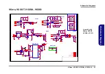
CRT  B  -  17

B.Schematic Diagrams

CRT

Sheet 16 of 39

CRT

Содержание W950BU

Страница 1: ...W950BU W955BU ...

Страница 2: ......

Страница 3: ...Preface I Preface Notebook Computer W950BU W955BU Service Manual ...

Страница 4: ...le or in part be reproduced translated transmitted or reduced to any machine readable form without prior consent from the vendor manufacturer or creators of this publica tion except for copies kept by the user for backup purposes Brand and product names mentioned in this publication may or may not be copyrights and or registered trademarks of their respective companies They are mentioned for ident...

Страница 5: ...vicing and or upgrading components of the W950BU W955BU series notebook PC The following information is included Chapter 1 Introduction provides general information about the location of system elements and their specifications Chapter 2 Disassembly provides step by step instructions for disassembling parts and subsystems and how to upgrade elements of the system Appendix A Part Lists Appendix B S...

Страница 6: ...to report a gas leak in the vicinity of the leak 4 Use only the power cord and batteries indicated in this manual Do not dispose of batteries in a fire They may explode Check with local codes for possible special disposal instructions 5 This product is intended to be supplied by a Listed Power Unit with an AC Input of 100 240V 50 60Hz DC Output of 19V 2 1A 40 Watts minimum AC DC Adapter CAUTION Th...

Страница 7: ... down properly and don t forget to save your work Remember to periodically save your data as data may be lost if the battery is depleted Do not expose the computer to any shock or vibration Do not place it on an unstable surface Do not place anything heavy on the computer Do not expose it to excessive heat or direct sunlight Do not leave it in a place where foreign matter or mois ture may affect t...

Страница 8: ...rpose If you do not have access to a compatible outlet have a qualified electrician install one When you want to unplug the power cord be sure to disconnect it by the plug head not by its wire Make sure the socket and any extension cord s you use can support the total current load of all the connected devices Before cleaning the computer make sure it is disconnected from any external power supplie...

Страница 9: ...ur hands or metal objects Battery Guidelines The following can also apply to any backup batteries you may have If you do not use the battery for an extended period then remove the battery from the computer for storage Before removing the battery for storage charge it to 60 70 Check stored batteries at least every 3 months and charge them to 60 70 Battery Disposal The product that you have purchase...

Страница 10: ...puter then plug the AC power cord into an outlet and connect the AC power cord to the AC DC adapter 6 Use one hand to raise the lid LCD to a comfortable viewing angle do not exceed 130 degrees use the other hand as illustrated in Figure 1 to support the base of the computer Note Never lift the computer by the lid LCD 7 Press the power button to turn the computer on 130 Figure 1 Opening the Lid LCD...

Страница 11: ...he System Memory RAM 2 11 Removing the M 2 SSD Module 2 13 Removing the Keyboard 2 14 Removing the 3G Module 2 16 Removing the Wireless LAN Module 2 17 Wireless LAN and Combo Module Cables 2 18 Removing the CCD 2 19 Part Lists A 1 Part List Illustration Location A 2 Top W950BU A 3 Top W955BU A 4 Bottom W950BU A 5 Bottom W955BU A 6 LCD W950BU A 7 LCD W955BU A 8 DVD DUAL W950BU A 9 DVD DUAL W955BU A...

Страница 12: ...DDQ VDDQ_VTT 1 5VS 1 8VS B 29 1 0V Series B 30 VCore VCCGT VCCSA VCCIO B 31 Charger DC In B 32 NCP81206 Regulator B 33 Audio Board B 34 Power SW Board B 35 Option BOM List B 36 Updating the FLASH ROM BIOS C 1 Download the BIOS C 1 Unzip the downloaded files to a bootable CD DVD or USB Flash drive C 1 Set the computer to boot from the external drive C 1 Use the flash tools to update the BIOS C 2 Re...

Страница 13: ... is shipped with the computer Operating systems e g Window 8 1 etc have their own manuals as do application softwares e g word processing and database programs If you have questions about those programs you should consult those manuals The W950BU W955BU series notebook is designed to be upgradeable See Disassembly on page 2 1 for a detailed description of the upgrade procedures for each specific c...

Страница 14: ...emory Expandable up to 16GB Compatible with 2GB 4GB or 8GB Modules The real memory operating frequency depends on the FSB of the processor LCD Options 15 6 39 62cm 16 9 HD 1366x768 FHD 1920x1080 Thickness 3 8mm Video Adapter Intel HD Graphics Dynamic Frequency Intel Dynamic Video Memory Technology Microsoft DirectX 12 Compatible Audio High Definition Audio Compliant Interface 2 Built In Speakers B...

Страница 15: ...le WLAN Bluetooth M 2 Modules Factory Option Intel Wireless AC 8265 Wireless LAN 802 11ac Bluetooth 4 1 Factory Option Intel Wireless AC 3168 Wireless LAN 802 11ac Bluetooth 4 0 Factory Option Intel Wireless AC 8260 Wireless LAN 802 11ac Bluetooth 4 0 Power Full Range AC DC Adapter AC Input 100 240V 50 60Hz DC Output 19V 2 1A 40W Removable 4 Cell Smart Lithium Ion Battery Pack 32WH Factory Option ...

Страница 16: ...Introduction External Locator Top View with LCD Panel Open Figure 1 Top View 1 PC Camera 2 PC Camera LED When the PC camera is in use the LED will be illuminated in red 3 Built In Microphone W950BU only 4 LCD 5 Power Button 6 Keyboard 7 Touchpad Buttons 5 2 4 7 1 3 6 ...

Страница 17: ...tor Front Right Side Views Figure 2 Front View 1 LED Indicator 2 Multi in 1 Card Reader Figure 3 Right Side View 1 Microphone In Jack 2 Headphone Out Jack 3 USB 2 0 Ports 4 Optical Device Drive Bay 5 Emergency Eject Hole 6 Security Lock Slot FRONT VIEW 1 2 RIGHT SIDE VIEW 1 2 3 6 4 5 3 ...

Страница 18: ...ear View 1 Introduction External Locator Left Side Rear View Figure 4 Left Side View 1 DC In Jack 2 RJ 45 LAN Jack 3 External Monitor Port 4 Vent 5 HDMI Out Port 6 USB 3 0 Ports LEFT SIDE VIEW 1 2 3 4 5 6 6 Figure 5 Rear View 1 Battery REAR VIEW 1 ...

Страница 19: ...om View 1 7 1 Introduction External Locator Bottom View Figure 6 Bottom View 1 Battery 2 Vent 3 Speakers Overheating To prevent your com puter from overhea ting make sure no thing blocks any vent while the computer is in use 1 2 3 3 2 2 ...

Страница 20: ...Introduction 1 8 Mainboard Overview Top Key Parts 1 Introduction Mainboard Overview Top Key Parts Figure 7 Mainboard Top Key Parts 1 KBC ITE IT8587 2 3 1 ...

Страница 21: ... Key Parts 1 M 2 Card Connector 3G 2 CPU 3 Memory Slots DDR3L SO DIMM 4 CMOS Battery 5 M 2 Card Connector SSD 6 M 2 Card Connector WLAN Introduction Mainboard Overview Bottom Key Parts 1 9 1 Introduction Mainboard Overview Bottom Key Parts ...

Страница 22: ... Mainboard Overview Top Connectors 1 Introduction Mainboard Overview Top Connectors Figure 9 Mainboard Top Connectors 1 HDMI Out Port 2 USB Port 3 0 3 Keyboard Cable Connector 4 Audio Board Cable Connector 11 1 2 4 3 2 ...

Страница 23: ...ion Mainboard Overview Bottom Connectors Figure 10 Mainboard Bottom Connectors 1 ODD Connector 2 HDD Connector 3 Multi in 1 Card Reader 4 External Monitor Port 5 RJ 45 LAN Jack 6 DC In Jack 7 CCD Connector 8 LCD Cable Connector 9 Battery Connector 11 1 2 4 6 7 3 5 8 9 ...

Страница 24: ...Introduction 1 12 1 Introduction ...

Страница 25: ...assembly process easier each section may have a box in the page margin Information contained under the figure will give a synopsis of the sequence of procedures involved in the disassembly procedure A box with a lists the relevant parts you will have after the disassembly process is complete Note The parts listed will be for the dis assembly procedure listed ONLY and not any previous disassembly s...

Страница 26: ...c ing the connection make sure the connector is oriented in the same way The pin1 side is usually not indicated Pressure sockets for multi wire connectors To release this connector type grasp it at its head and gently rock it from side to side as you pull it out Do not pull on the wires themselves When replacing the connection do not try to force it The socket only fits one way Pressure sockets fo...

Страница 27: ... pull on the wire 6 Peripherals Turn off and detach any peripherals 7 Beware of static discharge ICs such as the CPU and main support chips are vulnerable to static electricity Before handling any part in the computer discharge any static electricity inside the computer When handling a printed circuit board do not use gloves or other materials which allow static electricity buildup We suggest that...

Страница 28: ...age 2 6 3 Remove the optical device page 2 8 4 Remove the caddy page 2 10 To remove the System Memory 1 Remove the battery page 2 5 2 Remove the HDD page 2 6 3 Remove the system memory page 2 11 To remove the M 2 SSD 1 Remove the battery page 2 5 2 Remove the HDD page 2 6 3 Remove the SSD page 2 13 To remove the Keyboard 1 Remove the battery page 2 5 2 Remove the HDD page 2 6 3 Remove the keyboard...

Страница 29: ...in the direction of the arrow Figure 1a 3 Slide the latch in the direction of the arrow and hold it in place Figure 1a 4 Slide the battery in the direction of the arrow Figure 1b 1 2 6 3 4 3 Battery Figure 1 Battery Removal a Slide the latch and hold it in place b Slide the battery out in the direction of the arrow a b 3 4 1 2 ...

Страница 30: ...he HDD assem bly HDD System Warning New HDD s are blank Before you begin make sure You have backed up any data you want to keep from your old HDD You have all the CD ROMs and FDDs re quired to install your op erating system and programs If you have access to the internet download the latest application and hardware driver up dates for the operating system you plan to in stall Copy these to a re mo...

Страница 31: ...sive cover from the hard disk Figure 3f 8 Reverse the process to install a new hard disk do not forget to replace all the screws and bottom cover 17 18 19 20 21 22 23 d f 22 23 e 19 17 18 21 20 18 HDD Assembly 22 Adhesive Cover 23 HDD 2 Screws Figure 3 HDD Assembly Removal cont d d Slightly lift and pull the HDD assembly in the di rection of the arrow e Lift the HDD assembly out of the bay f Remov...

Страница 32: ...2 6 2 Carefully pull out the optical device out of the bay at point Figure 4a 3 Carefully pry the bezel off the optical device at point Figure 4b 4 Separate the bezel and the optical device Figure 4c 1 2 4 3 4 1 Optical Device 4 Bezel 1 a b 4 3 c 2 Figure 4 Optical Device Removal a Pull out the optical de vice b Pry the bezel off the opti cal device c Separate the bezel and optical device ...

Страница 33: ... slide it into the computer the device only fits one way DO NOT FORCE IT The screw holes should line up Take care to avoid folding the connector underneath 7 Replace the bottom cover and tighten the screws 8 Restart the computer to allow it to automatically detect the new device 4 5 1 1 Optical Device 4 Bezel e d 5 4 1 Figure 5 Optical Device Assembly d Install the front bezel e Insert the optical...

Страница 34: ...ssembly 4 Lift the hard disk and connector out Figure 6c 5 Separate the hard disk and connector Figure 6d 6 Reverse the process to install a new HDD do not forget to replace the screws and bottom cover 7 Restart the computer to allow it to automatically detect the new device 1 2 3 8 9 10 9 10 1 Caddy 9 HDD 10 HDD Connector 6 Screws b 2 1 a 9 3 4 6 5 7 8 9 d c 10 10 Figure 6 Caddy 2nd HDD Removal a...

Страница 35: ...anded up to 8GB The SO DIMM modules supported are 1024MB and 2048MB DDR3L Modules The total memory size is automatically detected by the POST routine once you turn on your computer Memory Upgrade Process 4 RAM Module 1 Turn off the computer turn it over to remove the battery page 2 5 and bottom cover page 2 6 2 The RAM modules will be visible at point on the mainboard Figure 7b 3 Gently pull the t...

Страница 36: ... slot 6 The module will only fit one way as defined by its pin alignment Make sure the module is seated as far into the slot as it will go DO NOT FORCE IT it should fit without much pressure 7 Replace the bottom case and the screws see page 2 6 8 Restart the computer to allow the BIOS to register the new memory configuration as it starts up d 4 Figure 8 RAM Module Assembly d Insert the RAM mod ule...

Страница 37: ... page 2 5 2 The M 2 SSD module will be visible at point on the mainboard Figure 9a 3 Remove the screw Figure 9b 4 The M 2 SSD module Figure 9c will pop up and you can remove it from the computer 1 2 3 b c a 2 3 1 3 3 M2 SSD Module 1 Screw Figure 9 M 2 SSD Module Removal a Locate the M 2 SSD b Remove the screw c The M 2 SSD module will pop up ...

Страница 38: ...rd Figure 10c 4 Carefully lift the keyboard up being careful not to bend the keyboard ribbon cable Disconnect the keyboard rib bon cable from the locking collar socket Figure 10d 5 Carefully lift up the keyboard off the computer Figure 10e 1 2 3 4 5 6 4 b c a 6 1 4 5 6 4 2 3 4 Keyboard 2 Screws Figure 10 Keyboard Removal a Remove screw and re lease the keyboard by pressing at point b Disconnect th...

Страница 39: ... 11d 7 Insert the keyboard at point and then slide the keyboard in at point and Figure 11e 8 Tighten the screws to secure the keyboard Figure 11f 8 7 4 9 10 11 12 13 d 9 8 8 e 7 9 10 11 f 12 13 4 4 Keyboard 2 Screws Figure 11 Keyboard Assembly d Connect the keyboard ribbon cable to the lock ing collar socket e Insert the keyboard at point and slide it in f Tigthen the screws 9 ...

Страница 40: ... 12a 3 Carefully disconnect the cables and then remove the screw Figure 12b 4 The 3G module Figure 12c will pop up and you can remove it from the computer 1 2 3 4 5 b c a 2 3 5 1 5 4 5 Wireless LAN Module 1 Screw Figure 12 3G Module Removal a Locate the 3G b Disconnect the cable and remove the screw c The 3G module will pop up and lift it out of the computer Note Make sure you reconnect the antenn...

Страница 41: ...ure 13a 3 Carefully disconnect the cables and then remove the screw Figure 13b 4 The Wireless LAN module Figure 13c will pop up and you can remove it from the computer 1 2 3 4 5 b c a 2 3 5 1 5 4 5 Wireless LAN Module 1 Screw Figure 13 Wireless LAN Module Removal a Locate the WLAN b Disconnect the cable and remove the screw c The WLAN module will pop up and lift it out of the computer Note Make su...

Страница 42: ...bo modules are not labelled The cables covers each cable will have either a black or transparent cable cover are color coded for identification as outlined in the table below Cable 1 is usually connected to antenna 1 Main on the module and cable 2 to antenna 2 Aux Module Type Antenna Type Cable Color Cable Cover Type WLAN WLAN Bluetooth Combo WM 1 Black Transparent WM 2 Gray WM 3 White ...

Страница 43: ... the top case up forming a 90 degree angle Push the LCD front cover upwards before carefully lifting it up 4 Remove the LCD front cover Figure 14c 1 4 5 5 c b a 1 2 5 3 4 5 5 LCD Front Cover Figure 14 CCD Removal a Run your fingers around the inner frame of the LCD panel at the points indicated by the arrows b Lay the computer down on a flat surface with the top case up forming a 90 degree angle P...

Страница 44: ...e CCD 2 Disassembly 5 Disconnect the cable 6 Remove the CCD module Figure 15f 7 Reverse the process to install a new CCD module 6 7 e d 7 6 7 CCD Module Figure 15 CCD Removal cont d d Disconnect the cable e Remove the CCD mod ule ...

Страница 45: ...ers Your organization may use a different system so be sure to cross check any relevant documentation Note Some assemblies may have parts in common especially screws However the part lists DO NOT indicate the total number of duplicated parts used Note Be sure to check any update notices The parts shown in these illustrations are appropriate for the system at the time of publication Over the produc...

Страница 46: ... where to find the appropriate part list illustration Table A 1 Part List Illustration Location Part W950BU W955BU Top page A 3 page A 4 Bottom page A 5 page A 6 LCD page A 7 page A 8 DVD Dual Drive page A 9 page A 10 Dummy ODD page A 11 HDD page A 12 page A 12 2nd HDD page A 14 ...

Страница 47: ...Top W950BU A 3 A Part Lists Top W950BU Figure A 1 Top W950BU ...

Страница 48: ...A 4 Top W955BU A Part Lists Top W955BU Figure A 2 Top W955BU ...

Страница 49: ...Bottom W950BU A 5 A Part Lists Bottom W950BU Figure A 3 Bottom W950BU ...

Страница 50: ...A 6 Bottom W955BU A Part Lists Bottom W955BU Figure A 4 Bottom W955BU ...

Страница 51: ...LCD W950BU A 7 A Part Lists LCD W950BU Figure A 5 LCD W950BU ...

Страница 52: ...A 8 LCD W955BU A Part Lists LCD W955BU Figure A 6 LCD W955BU ...

Страница 53: ...DVD DUAL W950BU A 9 A Part Lists DVD DUAL W950BU Figure A 7 DVD DUAL W950BU ...

Страница 54: ...A 10 A Part Lists DVD DUAL W955BU Figure A 8 DVD DUAL W955BU ...

Страница 55: ...Dummy ODD W950BU A 11 A Part Lists Dummy ODD W950BU Figure A 9 Dummy ODD W950BU ...

Страница 56: ...A 12 HDD W950BU A Part Lists HDD W950BU Figure A 10 HDD W950BU ...

Страница 57: ...HDD W955BU A 13 A Part Lists HDD W955BU Figure A 11 HDD W955BU ...

Страница 58: ...A 14 2nd HDD W950BU A Part Lists 2nd HDD W950BU Figure A 12 2nd HDD W950BU ...

Страница 59: ...e B 32 Skylake ULT Power Maint Page B 7 HDMI RJ45 Fan Page B 20 NCP81206 Regulator Page B 33 Skylake ULT GPIOS I2C EMMC Page B 8 M 2 WLAN 3G SSD Page B 21 Audio Board Page B 34 Skylake ULT PCIE USB SATA Page B 9 Audio Codec Page B 22 Power SW Board Page B 35 Skylake ULT Power 1 Page B 10 USB 3 0 G Sensor TPM Page B 23 Option BOM List Page B 36 Skylake ULT Power 2 Page B 11 KBC ITE IT8587 Page B 24...

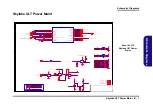
Страница 60: ...5 SATA HDD SHEET 25 25 MHz USB2 0 PORT3 SHEET 22 USB3 0 USB2 0 PORT1 SHEET 22 USB3 0 5 Gbps USB3 0 PORT1 USB3 0 PORT3 DDR3 DDR3 RTD2136N Power 1 0V 1 5V 3 3V VCORE VR12 5 Power 1 35V DDR 1 35V 1 5VS 1 8VS SHEET 28 SHEET 17 7 MS 9 SL SHEET 20 SPI SYSTEM SMBUS G SENSER SHEET 22 6 5 3 VIA 10 4 VIA Optional SATA ODD SHEET 25 32 768KHz M 2 3G WLAN USB2_2 EDP TO LVDS RTD2168 DP TO VGA SHEET 16 HDMI PS82...

Страница 61: ... Rev Date Sheet of 1 0 02 KBL ULT DISPLAY MISC A3 2 38 Wednesday August 24 2016 ᙔ Ϻ ႝ တ DMFWP DP 6 7P W94J3 003 6 71 W94J0 D02B Title Size Document Number Rev Date Sheet of 1 0 02 KBL ULT DISPLAY MISC A3 2 38 Wednesday August 24 2016 ᙔ Ϻ ႝ တ DMFWP DP 6 7P W94J3 003 6 71 W94J0 D02B R612 100K_04 R594 51_04 R599 49 9_1 _04 R423 51_04 R331 10K_04 R289 1K_04 R616 0_04 R430 0_04 R595 51_04 R589 100K_04 ...

Страница 62: ...17 DDR0_DQ 33 AW65 DDR0_DQ 18 DDR0_DQ 34 AW63 DDR0_DQ 19 DDR0_DQ 35 AY63 DDR0_DQ 20 DDR0_DQ 36 BA65 DDR0_DQ 21 DDR0_DQ 37 AY65 DDR0_DQ 22 DDR0_DQ 38 BA63 DDR0_DQ 23 DDR0_DQ 39 BB63 DDR0_DQ 24 DDR0_DQ 40 BA61 DDR0_DQ 25 DDR0_DQ 41 AW61 DDR0_DQ 26 DDR0_DQ 42 BB59 DDR0_DQ 27 DDR0_DQ 43 AW59 DDR0_DQ 28 DDR0_DQ 44 BB61 DDR0_DQ 29 DDR0_DQ 45 AY61 DDR0_DQ 30 DDR0_DQ 46 BA59 DDR0_DQ 31 DDR0_DQ 47 AY59 DDR...

Страница 63: ...P_D23 I2S_MCLK J5 I2S1_SFRM AY20 I2S1_TXD AW20 GPP_F1 I2S2_SFRM AK7 GPP_F0 I2S2_SCLK AK6 GPP_F2 I2S2_TXD AK9 GPP_F3 I2S2_RXD AK10 GPP_D19 DMIC_CLK0 H5 GPP_D20 DMIC_DATA0 D7 GPP_D17 DMIC_CLK1 D8 GPP_D18 DMIC_DATA1 C8 GPP_B14 SPKR AW5 GPP_G0 SD_CMD AB11 GPP_G1 SD_DATA0 AB13 GPP_G2 SD_DATA1 AB12 GPP_G3 SD_DATA2 W12 GPP_G4 SD_DATA3 W11 GPP_G5 SD_CD W10 GPP_G6 SD_CLK W8 GPP_G7 SD_WP W7 GPP_A17 SD_PWR_E...

Страница 64: ...ent Number Rev Date Sheet of 1 0 05 KBL ULT LPC SPI SMB A3 5 38 Wednesday August 24 2016 ᙔ Ϻ ႝ တ DMFWP DP 6 7P W94J3 003 6 71 W94J0 D02B Title Size Document Number Rev Date Sheet of 1 0 05 KBL ULT LPC SPI SMB A3 5 38 Wednesday August 24 2016 ᙔ Ϻ ႝ တ DMFWP DP 6 7P W94J3 003 6 71 W94J0 D02B R406 2 2K_04 R93 1K_04 R110 499_1 _04 R95 1K_1 _04 R462 100K_04 S D G Q10B MTDK5S6R 5 3 4 R101 1K_04 R395 10mi...

Страница 65: ...te Sheet of 1 0 06 KBL ULT POWER MAMT A3 6 38 Wednesday August 24 2016 ᙔ Ϻ ႝ တ DMFWP DP 6 7P W94J3 003 6 71 W94J0 D02A Title Size Document Number Rev Date Sheet of 1 0 06 KBL ULT POWER MAMT A3 6 38 Wednesday August 24 2016 ᙔ Ϻ ႝ တ DMFWP DP 6 7P W94J3 003 6 71 W94J0 D02A Title Size Document Number Rev Date Sheet of 1 0 06 KBL ULT POWER MAMT A3 6 38 Wednesday August 24 2016 ᙔ Ϻ ႝ တ DMFWP DP 6 7P W94...

Страница 66: ...04 R67 10K_04 R47 1K_04 R121 10K_04 R98 49 9K_1 _04 R53 1K_04 R234 10K_04 R105 49 9K_1 _04 R23 20K_1 _04 R113 10K_04 R51 1K_04 SKL_ULT LPSS ISH 6 OF 20 REV 1 U55F KBL_ULT BGA GPP_A12 BM_BUSY ISH_GP6 AP13 GPP_A18 ISH_GP0 AY8 GPP_A19 ISH_GP1 BA8 GPP_A20 ISH_GP2 BB7 GPP_A21 ISH_GP3 BA7 GPP_A22 ISH_GP4 AY7 GPP_A23 ISH_GP5 AW7 GPP_B15 GSPI0_CS AN8 GPP_B16 GSPI0_CLK AP7 GPP_B17 GSPI0_MISO AP8 GPP_B18 GS...

Страница 67: ...DMFWP DP 6 7P W94J3 003 6 71 W94J0 D02B R640 0_04 R374 100K_04 R581 0_04 R534 10K_04 R385 10K_04 R641 0_04 R609 0_04 R131 113_1 _04 R606 0_04 C563 0 22u_10V_X5R_04 C494 0 1u_10V_X7R_04 C287 0 1u_10V_X7R_04 R582 0_04 R614 0_04 R591 10K_04 R642 0_04 C288 0 1u_10V_X7R_04 C557 0 22u_10V_X5R_04 R576 10K_04 C299 0 1u_10V_X7R_04 R45 100_1 _04 R590 200K_04 R41 0_04 C560 0 22u_10V_X5R_04 C300 0 1u_10V_X7R_...

Страница 68: ... 3V_X5R_04 C1078 22u_6 3V_X5R_08 C447 2 2u_6 3V_X5R_04 C345 22u_6 3V_X5R_06 C573 330uF_2 5V_12m_6 6 6 6 4 2 C1100 22u_6 3V_X5R_08 C1101 22u_6 3V_X5R_06 C1021 1u_6 3V_X5R_04 C34 22u_6 3V_X5R_06 C295 22u_6 3V_X5R_06 C1096 22u_6 3V_X5R_06 C508 1u_6 3V_X5R_04 C1024 1u_6 3V_X5R_04 C66 22u_6 3V_X5R_08 C1095 22u_6 3V_X5R_06 C1080 47u_6 3V_X5R_08 C35 22u_6 3V_X5R_06 C1094 22u_6 3V_X5R_06 R958 33_04 C343 2...

Страница 69: ...3V_X5R_04 R127 10K_04 C62 1u_6 3V_X5R_04 L36 HCB1608KF 121T30 L72 15mil_short_06 C326 2 2u_6 3V_X5R_04 C318 2 2u_6 3V_X5R_04 L11 20mil_04 C503 1u_6 3V_X5R_04 L8 15mil_short_06 L12 15mil_short_06 C504 1u_6 3V_X5R_04 C31 22u_6 3V_X5R_08 C501 1u_6 3V_X5R_04 L74 15mil_short_06 L51 15mil_short_06 SKL_ULT CPU POWER 4 OF 4 15 OF 20 REV 1 U55O KBL_ULT BGA GPP_B0 CORE_VID0 AN11 GPP_B1 CORE_VID1 AN13 VCCCLK...

Страница 70: ... BGA RSVD_AW69 AW69 RSVD_AW68 AW68 RSVD_AU56 AU56 RSVD_AW48 AW48 RSVD_C7 C7 RSVD_U12 U12 RSVD_U11 U11 RSVD_H11 H11 RSVD_F6 F6 RSVD_E3 E3 RSVD_C11 C11 RSVD_B11 B11 RSVD_A11 A11 RSVD_D12 D12 RSVD_C12 C12 RSVD_F52 F52 SKL_ULT GND 2 OF 3 17 OF 20 REV 1 U55Q KBL_ULT BGA VSS AT63 VSS AT68 VSS AT71 VSS AU10 VSS AU15 VSS AU20 VSS AU32 VSS AU38 VSS AV1 VSS AV68 VSS AV69 VSS AV70 VSS AV71 VSS AW10 VSS AW12 ...

Страница 71: ...CGT W66 VCCGT W67 VCCGT W68 VCCGT W69 VCCGT W70 VCCGT W71 VCCGT Y62 VCCGTX_AK42 AK42 VCCGTX_AK43 AK43 VCCGTX_AK45 AK45 VCCGTX_AK46 AK46 VCCGTX_AK48 AK48 VCCGTX_AK50 AK50 VCCGTX_AK52 AK52 VCCGTX_AK53 AK53 VCCGTX_AK55 AK55 VCCGTX_AK56 AK56 VCCGTX_AK58 AK58 VCCGTX_AK60 AK60 VCCGTX_AK70 AK70 VCCGTX_AL43 AL43 VCCGTX_AL46 AL46 VCCGTX_AL50 AL50 VCCGTX_AL53 AL53 VCCGTX_AL56 AL56 VCCGTX_AL60 AL60 VCCGTX_AM...

Страница 72: ... 5V_12m_6 6 6 6 4 2 C574 1000p_50V_X7R_04 C143 1u_6 3V_X5R_04 R149 2 2_1 _06 RN1 10K_8P4R_04 1 2 3 4 5 6 7 8 R143 0_04 R147 470_04 C147 10u_6 3V_X5R_06 C133 2 2u_6 3V_X5R_04 C137 10u_6 3V_X5R_06 C159 0 1u_10V_X5R_04 C150 0 022u_16V_X7R_04 C144 1u_6 3V_X5R_04 C126 0 022u_16V_X7R_04 C141 1u_6 3V_X5R_04 C145 1u_6 3V_X5R_04 R153 0_04 C10 0 01u_50V_X7R_04 R145 24 9_1 _04 R154 1 82K_1 _04 C146 10u_6 3V_...

Страница 73: ...92 A5 91 A6 90 A7 86 A8 89 A9 85 A10 AP 107 A11 84 A12 BC 83 A13 119 A14 80 A15 78 DQ0 5 DQ1 7 DQ2 15 DQ3 17 DQ4 4 DQ5 6 DQ6 16 DQ7 18 DQ8 21 DQ9 23 DQ10 33 DQ11 35 DQ12 22 DQ13 24 DQ14 34 DQ15 36 DQ16 39 DQ17 41 DQ18 51 DQ19 53 DQ20 40 DQ21 42 DQ22 50 DQ23 52 DQ24 57 DQ25 59 DQ26 67 DQ27 69 DQ28 56 DQ29 58 DQ30 68 DQ31 70 DQ32 129 DQ33 131 DQ34 141 DQ35 143 DQ36 130 DQ37 132 DQ38 140 DQ39 142 DQ4...

Страница 74: ... ႝ တ DMFWP DP 6 7P W94J3 003 6 71 W94J0 D02B Title Size Document Number Rev Date Sheet of 1 0 15 PANEL INVERTER A3 15 38 Wednesday August 24 2016 ᙔ Ϻ ႝ တ DMFWP DP 6 7P W94J3 003 6 71 W94J0 D02B R343 100K_04 C15 0 1u_10V_X5R_04 R267 100K_04 J_LCD2 50238 0407N 001 11 11 12 12 13 13 14 14 15 15 16 16 17 17 18 18 19 19 20 20 21 21 22 22 23 23 24 24 25 25 26 26 27 27 28 28 29 29 30 30 31 31 32 32 33 33...

Страница 75: ...2B R1506 0_04 R428 75_1 _04 C532 0 1u_10V_X5R_04 U105 U74LVC1G125G AL5 R 1 2 5 4 3 C1467 2 2u_6 3V_X5R_04 R1497 4 7K_04 C525 10p_50V_NPO_04 C480 0 1u_10V_X5R_04 L39 FCM1005MF 600T01 C246 1u_6 3V_X5R_04 X8 FSX3M_27MHz 1 2 3 4 C526 1000p_50V_X7R_04 R1508 0_04 R1522 10mil_04 C281 1u_6 3V_X5R_04 R408 4 7K_04 C1468 10u_6 3V_X5R_06 C324 15p_50V_NPO_04 R310 2 2K_04 R1502 4 7K_04 R390 100K_04 C420 15p_50V...

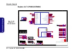
Страница 76: ...HTNESS_R LVDS LCLKP VDD12 LVDS LCLKN VDDRX_LVDS SW_OUT SW_OUT LVDS L2N GND GND RLV_CFG ENBLT SMD_EDP_DAT RLV_LNK GPIO0 SMC_EDP_CLK PWM_IN REXT_LVDS RLV_AMP DAUXn DAUXp LVDS UCLKN VDDIO_LVDS 3 3VS GND_LVDS 3 3VS GND_LVDS 3 3VS GND_LVDS GND_LVDS GND_LVDS GND_LVDS GND_LVDS GND_LVDS GND_LVDS GND_LVDS GND_LVDS GND_LVDS GND_LVDS GND_LVDS LVDS LCLKP 15 LVDS U2P 15 LVDS LCLKN 15 LVDS U2N 15 LVDS L2P 15 LV...

Страница 77: ...1B A3 18 38 Wednesday August 24 2016 ᙔ Ϻ ႝ တ DMFWP DP 6 7P W94J3 003 6 71 W94J0 D02B Title Size Document Number Rev Date Sheet of 1 0 18 CARD READER LAN_RTL8411B A3 18 38 Wednesday August 24 2016 ᙔ Ϻ ႝ တ DMFWP DP 6 7P W94J3 003 6 71 W94J0 D02B Title Size Document Number Rev Date Sheet of 1 0 18 CARD READER LAN_RTL8411B A3 18 38 Wednesday August 24 2016 ᙔ Ϻ ႝ တ DMFWP DP 6 7P W94J3 003 6 71 W94J0 D0...

Страница 78: ...ႝ တ DMFWP DP 6 7P W94J3 003 6 71 W94J0 D02B Title Size Document Number Rev Date Sheet of 1 0 19 HDMI RJ45 FAN Custom 19 38 Wednesday August 24 2016 ᙔ Ϻ ႝ တ DMFWP DP 6 7P W94J3 003 6 71 W94J0 D02B R666 499_1 _04 R573 0_04 R497 4 7K_04 L32 NS892402 TCT1 1 2 TD1 3 TD1 TCT2 4 5 TD2 6 TD2 TCT3 7 8 TD3 9 TD3 TCT4 10 11 TD4 12 TD4 13 MX4 14 MX4 MCT4 15 16 MX3 17 MX3 MCT3 18 19 MX2 20 MX2 MCT2 21 22 MX1 2...

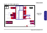
Страница 79: ...SATA B 43 PETp0 SATA A 49 PETn0 SATA A 47 PERn0 SATA B 41 GND5 39 GND6 45 ANTCTL1 I 1 8V 61 ANTCTL2 I 1 8V 63 ANTCTL3 I 1 8V 65 CONFIG_2 75 GPIO_1 IO 1 8V 42 GPIO_2 IO 1 8V 44 GPIO_3 IO 1 8V 46 GPIO_4 IO 1 8V 48 COEX2 I O 1 8V 62 3 3V3 72 3 3V4 74 C70 1u_6 3V_X5R_04 R1494 0_04 R271 10mil_short R389 0_04 R669 10K_04 C155 0 1u_16V_Y5V_04 C261 22p_50V_NPO_04 R1495 0_04 R752 10K_04 C552 0 1u_10V_X7R_0...

Страница 80: ... 003 6 71 W94J0 D02B Title Size Document Number Rev Date Sheet of 1 0 21 AUDIO CODEC_ALC269_VC2 A3 21 38 Wednesday August 24 2016 ᙔ Ϻ ႝ တ DMFWP DP 6 7P W94J3 003 6 71 W94J0 D02B C436 2 2u_6 3V_X5R_04 C428 10p_50V_NPO_04 R512 39 2K_1 _04 Q21 MTN7002ZHS3 G D S C429 10u_6 3V_X5R_06 L75 HCB1005KF 121T20 C439 0 1u_16V_Y5V_04 C425 10p_50V_NPO_04 C203 470p_50V_X7R_04 C448 10u_6 3V_X5R_06 L29 HCB1608KF 30...

Страница 81: ...ednesday August 24 2016 ᙔ Ϻ ႝ တ DMFWP DP 6 7P W94J3 003 6 71 W94J0 D02B Title Size Document Number Rev Date Sheet of 1 0 22 USB 3 0 PORT G SENSOR TPM A3 22 38 Wednesday August 24 2016 ᙔ Ϻ ႝ တ DMFWP DP 6 7P W94J3 003 6 71 W94J0 D02B Title Size Document Number Rev Date Sheet of 1 0 22 USB 3 0 PORT G SENSOR TPM A3 22 38 Wednesday August 24 2016 ᙔ Ϻ ႝ တ DMFWP DP 6 7P W94J3 003 6 71 W94J0 D02B C202 22u...

Страница 82: ...4 R203 10_04 Q19 MTN7002ZHS3 G D S R182 10K_04 R275 10K_04 R181 10K_04 R249 100K_04 C154 0 1u_16V_Y5V_04 R210 100K_04 C174 10p_50V_NPO_04 R256 47_04 R491 10K_04 C184 1u_6 3V_X5R_04 D2 BAV99 RECTIFIER A C AC R169 0_04 R176 1K_04 R299 10K_04 C190 10u_6 3V_X5R_06 D3 BAV99 RECTIFIER A C AC IT8587 U4B IT8587E FX GPA0 PWM0 5VT 24 GPA2 PWM2 5VT 28 GPA3 PWM3 5VT 29 GPA4 PWM4 5VT 30 GPI2 ADC2 68 GPI5 ADC5 ...

Страница 83: ... 003 6 71 W94J0 D02B Title Size Document Number Rev Date Sheet of 1 0 24 CCD MIC LID I O CONNECTOR A3 24 38 Wednesday September 07 2016 ᙔ Ϻ ႝ တ DMFWP DP 6 7P W94J3 003 6 71 W94J0 D02B C2 1u_6 3V_X5R_04 J_CCD1 85205 08001 PCB Footprint 85205 08001R 1 2 3 4 5 6 7 8 D4 AVL18S02015 1 2 C1 1u_10V_Y5V_06 C259 0 1u_16V_Y5V_04 C215 2 2u_6 3V_X5R_04 R241 0_04 C88 0 1u_16V_Y5V_04 C201 10u_6 3V_X5R_06 U17 UP...

Страница 84: ...t of 1 0 25 HDD ODD LED A3 25 38 Wednesday August 24 2016 ᙔ Ϻ ႝ တ DMFWP DP 6 7P W94J3 003 6 71 W94J0 D02B Title Size Document Number Rev Date Sheet of 1 0 25 HDD ODD LED A3 25 38 Wednesday August 24 2016 ᙔ Ϻ ႝ တ DMFWP DP 6 7P W94J3 003 6 71 W94J0 D02B D9 RY SP190YG34 5M A C U39 MC74VHC1G08DFT2G 1 2 5 4 3 C350 10u_6 3V_X5R_06 RN2 220_8P4R_04 1 2 3 4 5 6 7 8 C369 10u_6 3V_X5R_06 R300 0_04 J_HDD2 508...

Страница 85: ...0mil 1 2 EM5209 U46 CT2 10 OUT2 8 EN2 5 VBIAS 4 IN2 6 GND 11 EN1 3 CT1 12 OUT1 13 IN1 1 IN1 2 OUT1 14 IN2 7 OUT2 9 GND 15 U108 P2808B0 VA 1 VIN 2 M_BTN 3 INSTANT ON 4 GND 5 PWR_SW 6 DD_ON_LATCH 7 VIN1 8 R657 10K_04 PR178 10K_04 R1591 1K_04 Q126 MTN7002ZHS3 G D S R656 10K_04 C572 1000p_50V_X7R_04 C612 0 1u_10V_X7R_04 C568 470p_50V_X7R_04 C584 1u_6 3V_X5R_04 R1594 100K_04 C746 220p_50V_NPO_04 R1605 ...

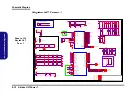
Страница 86: ...MB17A03V 1 2 7 8 9 PR279 20mil_04 PC205 4 7u_25V_X5R_08 R1509 10K_04 PQ67A EMB17A03V 3 4 5 6 10 PD28 RB751S 40C2 A C Q79 MTN7002ZHS3 G D S PR293 2_06 PQ67B EMB17A03V 1 2 7 8 9 PC207 15u_25V_6 3 4 4 PC219 4 7u_25V_X5R_08 PU11 TPS51125ARGER VREF 3 EN1 1 VFB1 2 TONSEL 4 LDO5 17 LGATE1 19 PHASE1 20 VFB2 5 UGATE2 10 VCLK 18 BOOT2 9 EN2 6 VO2 7 LDO3 8 PHASE2 11 LGATE2 12 EN0 13 SKIPSEL 14 GND 15 VIN 16 ...

Страница 87: ...1 47K_04 PU12 uP6163 VTTGND 1 VLDOIN 23 VTT 24 VTTSNS 2 GND 3 MODE 4 VTTREF 5 VCC5 14 PGOOD 13 S5 11 S3 10 VDDQSET 9 VDDQSNS 8 COMP 6 CS 16 PGND 18 DRVL 19 LL 20 DRVH 21 VBST 22 PVCC5 15 CS_GND 17 NC 7 NC 12 GND 25 PR308 10K_04 R1513 47K_04 PR298 20mil_04 R1519 0_04 PU13 APL5101 15AI TRG OUT 1 GND 2 IN 3 PC221 0 1u_50V_Y5V_06 C1471 0 1u_10V_X7R_04 PU14 G9661 25ADJF11U GND 8 VCNTL 4 NC 5 VIN 3 VOUT...

Страница 88: ...sday August 24 2016 ᙔ Ϻ ႝ တ DMFWP DP 6 7P W94J3 003 6 71 W94J0 D02B R1530 100K_04 R1529 100K_04 R654 47K_04 PJ52 OPEN 1mm 1 2 PR324 0_04 PR323 10K_04 PC254 1u_6 3V_X5R_04 C583 1u_6 3V_X5R_04 PR321 2 2_04 Q133 MTN7002ZHS3 G D S PQ72B EMB17A03V 1 2 7 8 9 R1606 10K_04 PR327 10mil_04 PD31 CSOD140SH A C PC256 1u_6 3V_X5R_04 C593 0 1u_16V_Y5V_04 EM5209 U48 CT2 10 OUT2 8 EN2 5 VBIAS 4 IN2 6 GND 11 EN1 3 ...

Страница 89: ... G D S PQ87 MDU1512 ULTRASO 8 G D S PC247 1000p_50V_X7R_04 PC325 4 7u_25V_X5R_08 PC335 390uF_2 5V_10m_6 3 6 PR328 2 2_06 C453 10u_6 3V_X5R_06 PC96 0 1u_50V_Y5V_06 PR372 20mil_04 PC289 1000p_50V_X7R_04 PC104 220u_25V_6 3 12 PC290 1000p_50V_X7R_04 PR371 20mil_04 PR333 5 1_06 U32 M5938 EN 2 GATE 1 VIN 9 VOUT 8 VBIAS 4 GND 3 VOUT 7 VOUT 6 VOUT 5 PC291 1000p_50V_X7R_04 PC288 1000p_50V_X7R_04 R1588 10K_...

Страница 90: ...74 100K_04 PC178 4 7u_25V_X5R_08 PR253 51_04 PC170 0 1u_50V_Y5V_06 PR313 0_04 PQ61 EMB20P03V 4 6 2 5 7 3 1 8 EMC3 30p_50V_NPO_04 PR272 300K_1 _04 PR254 0_04 PR243 100K_04 PR334 0_04 PR273 20K_1 _04 PR264 24K_1 _04 PC165 0 1u_50V_Y5V_06 PD24 ZD5245BS2 A C PC166 1500p_50V_04 PU10 OZ8685LN 3A BST 13 VAC 30 VDDP 29 IACM 32 SDA 11 ICHP 4 ICHM 1 SCL 10 IAC 6 IACP 31 ACAV 9 IBSET 5 PMON 3 PROCHOT 12 PSYS...

Страница 91: ...7 1K_1 _04 PR1302 19 1K_1 _04 PR1357 0_04 PC278 470p_50V_X7R_04 PR1335 165K_1 _04 PC99 2200p_50V_X7R_04 PR1320 0_04 PR1315 7 5K_1 _06 PR1332 20K_1 _04 PR1308 100_04 PR1322 1K_1 _04 C1529 20p_50V_NPO_04 PC97 0 1u_50V_Y5V_06 PC265 1000p_50V_X7R_04 PR1293 100_04 R188 78 7K_1 _06 1 2 PR1300 2_06 PC262 220p_50V_NPO_04 PR1295 1 82K_1 _04 PR1294 100_04 PR1324 100K_1 _04 PC276 0 01u_50V_X7R_04 PR1298 2_06...

Страница 92: ...day September 21 2016 Title Size Document Number Rev Date Sheet of 6 71 W95J9 D01 D02 03 AUDIO BOARD A3 3 4 Wednesday September 21 2016 Title Size Document Number Rev Date Sheet of 6 71 W95J9 D01 D02 03 AUDIO BOARD A3 3 4 Wednesday September 21 2016 AAR7 0_06 1AAR 0_04 AAJ_USB2 US04036BCA081 V 1 GND1 GND1 DATA_L 2 DATA_H 3 GND 4 GND2 GND2 GND4 GND4 GND3 GND3 2AAR 0_04 AAC12 180p_50V_NPO_04 AAL1 FC...

Страница 93: ...ocument Number Rev Date Sheet of 3 0 34 PWR SW BOARD W94 W95 A4 34 38 Wednesday August 24 2016 ᙔ Ϻ ႝ တ DMFWP DP 6 7P W94J3 003 6 71 W94LS D02 Title Size Document Number Rev Date Sheet of 3 0 34 PWR SW BOARD W94 W95 A4 34 38 Wednesday August 24 2016 ᙔ Ϻ ႝ တ DMFWP DP 6 7P W94J3 003 6 71 W94LS D02 SC1 0 1u_50V_Y5V_06 SJ_SW1 50578 0040N 001 PCB Footprint 85201 0405L 1 1 2 3 4 SD2 RY SP190DBW71 5A A C ...

Страница 94: ...ŝƚĞŵ Ȁ ͺʹͲͳ C226 C239 C240 C244 C225 C242 C241 C243 R278 R280 R281 R283 R284 R285 R286 R287 D90 D91 D5 D6 D7 Q22 Q42 R288 R488 R518 U5 C539 C538 C541 C540 C543 C542 C544 C546 R571 R569 C545 C484 C534 C536 C485 C483 C535 C537 R338 R339 R358 R570 R572 R573 R574 R575 R580 R585 R663 R664 R665 R666 R667 Q24 R609 R614 C560 C561 ƵŶĐƚŝŽŶ ŝƚĞŵ Ȁ Ǧ C450 C449 C451 R539 R538 ƵŶĐƚŝŽŶ ŝƚĞŵ Ȁ L37 J_TV1 C254 R584...

Страница 95: ... DC3 220u_6 3V_6 3 6 3 4 2 DC3 220u_6 3V_6 3 6 3 4 2 DR2 4 7K_04 DR2 4 7K_04 H2 C111D111N H2 C111D111N DR18 0_04 DR18 0_04 3DR 0_04 3DR 0_04 DC13 0 1u_16V_Y5V_04 DC13 0 1u_16V_Y5V_04 DC18 0 01u_16V_X7R_04 DC18 0 01u_16V_X7R_04 H3 C111D111N H3 C111D111N DC11 0 01u_16V_X7R_04 DC11 0 01u_16V_X7R_04 DR3 4 7K_04 DR3 4 7K_04 DR10 200K_1 _04 DR10 200K_1 _04 DR19 0_04 DR19 0_04 H4 C111D111N H4 C111D111N 4...

Страница 96: ...RNAL ODD BOARD W55 W95 A4 4 4 Wednesday September 21 2016 W95JU 4 in1 Title Size Document Number Rev Date Sheet of 6 71 W95KN D03 D03 04 EXTERNAL ODD BOARD W55 W95 A4 4 4 Wednesday September 21 2016 W95JU 4 in1 Title Size Document Number Rev Date Sheet of 6 71 W95KN D03 D03 04 EXTERNAL ODD BOARD W55 W95 A4 4 4 Wednesday September 21 2016 W95JU 4 in1 QC3 0 1u_16V_Y5V_04 1QAR 0_04 4QAR 0_04 3QAR 0_0...

Страница 97: ...eptember 21 2016 W95JU 4 in1 Title Size Document Number Rev Date Sheet of 6 71 W95KQ D02 D02 01 BATTERY CON BOARD W95 A3 1 4 Wednesday September 21 2016 W95JU 4 in1 Title Size Document Number Rev Date Sheet of 6 71 W95KQ D02 D02 01 BATTERY CON BOARD W95 A3 1 4 Wednesday September 21 2016 W95JU 4 in1 5BAR 0_04 M3 M MARK M5 M MARK 3BAR 0_04 H1 C111D111N M7 M MARK M4 M MARK H21 C111D111N 1 BH1 MTH6_0...

Страница 98: ... D01 D01 02 HALL SENSOR BOAR W55 W95 A3 2 4 Wednesday September 21 2016 W95JU 4 in1 Title Size Document Number Rev Date Sheet of 6 71 W95K1 D01 D01 02 HALL SENSOR BOAR W55 W95 A3 2 4 Wednesday September 21 2016 W95JU 4 in1 Title Size Document Number Rev Date Sheet of 6 71 W95K1 D01 D01 02 HALL SENSOR BOAR W55 W95 A3 2 4 Wednesday September 21 2016 W95JU 4 in1 LH2 C43D43N L_U1 MH248 ALFA ESO VCC 1 ...

Страница 99: ...d changes to the default BIOS settings Download the BIOS 1 Go to www clevo com tw and point to E Services and click E Channel 2 Use your user ID and password to access the appropriate download area BIOS and download the latest BIOS files the BIOS file will be contained in a batch file that may be run directly once unzipped for your computer model see sidebar for important information on BIOS versi...

Страница 100: ... to press any key to restart the system or turn the power off and then on again but make sure you remove the CD DVD USB flash drive from the CD DVD drive USB port before the computer restarts Restart the computer booting from the HDD 1 With the CD DVD USB flash drive removed from the CD DVD drive USB port the computer should restart from the HDD 2 Press F2 as the computer restarts to enter the BIO...

Отзывы: