Cleco LiveWire 943610PT Скачать руководство пользователя страница 11

Apex Tool Group

P2332BA | 2019-08

11

5
EN

5

Commissioning

The socket tray initially has no WLAN connection to the 
nutrunner control. The connection has to be configured via 
a USB interface port to a PC.

5.1 Opening the housing

The housing has to be opened for the following operations:

Changing inserts

Connecting the socket tray to a PC via a USB interface 
port

Fitting the socket tray

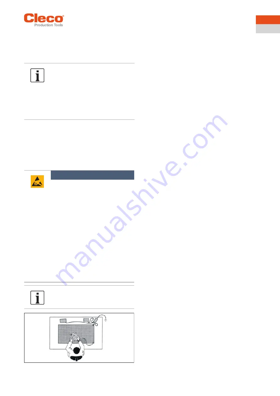
Fig. 5-1: ESD workplace

5.2 Configuring the socket tray

A detailed description of how to install the

 S168688


Live-

Wire Utilities

 software can be found in the installation


instructions P2372JH.

General procedure for configuring the socket tray:
1. Download the USB interface driver.
2. Download and install the 

LiveWire Utilities

 software 

package.

3. Start the 

LiveWire RF Settings

 program.

4. Start the socket tray.
5. Connecting the socket tray to a PC via a USB interface 

port. Make sure that the connection is only established 
after the socket tray has been started.

5.2.1 Installing the USB interface driver

Download the USB interface driver from the internet: 

http://software.apextoolgroup.com/current-
software-packages/pc-software/

A USB connector cable is needed to connect the socket 
tray to a PC. 
The related connector is located inside the housing of the 
socket tray on the controller board.
1. Switch off the socket tray.
2. Unscrew the four Phillips screws on the top of the 

housing and open the housing.
→ The controller board is located inside the housing 

close to the battery connector device. Make sure 
the socket tray is switched off before plugging in 
the USB connector cable. See 

Fig. 3-3: Internal 

control and function elements, Seite 7

, position 14.

3. Switch on the socket tray.
4. Plug the USB connector cable into the mini-USB 

socket on the controller board and connect it to the PC.

5. A suitable USB driver will automatically be installed on 

the PC. A internet connection is required.

5.2.2 Installing the 

LiveWire Utilities


software package

Download the 

LiveWire Utilities

 software package and the 

USB interface driver from the internet: 

http://software.apextoolgroup.com/current-
software-packages/pc-software/

To install the 

LiveWire Utilities


software package, follow 

the installation instructions that appear when the installa-
tion file is opened. 

A detailed description can be found in the Installation 
instructions P2372JH.

The backup battery is only partially 
charged for storage. For this reason, the 
socket tray displays a warning about the 
charge state of the backup battery during 
commissioning. During continuous opera-
tion, the backup battery recharges after 
24 - 48 hours and the warning disappears.
Operation and buffering during battery re-
placement are guaranteed even if the 
warning is displayed.

Note

Electrostatically sensitive component. 

The electronic assemblies of the Socket 
Tray WLAN can be destroyed or dam-
aged by electrostatic discharge (ESD). 
This can lead to immediate failure, or to 
malfunctions at a later date.

Note handling instructions.

To avoid damage when changing the 
LMC, make sure that there is a poten-
tial equalization between the person 
and the tool.

It may be necessary to set up the 
equipment in an ESD-protected envi-
ronment. Recommendation for an 
ESD workplace: Electrically conduc-
tive work surfaces, anti-static straps, 
appropriate furniture, clothing and 
footwear, and grounding of all compo-
nents

Do not touch any internal components.

Содержание LiveWire 943610PT

Страница 1: ...For additional product information visit our website at www ClecoTools com Instruction Manual P2332BA 2019 08 943620PT 943610PT WLAN socket tray...

Страница 2: ...able language or transmitted on electronic mechanical optical or other media without the express permission of the Apex Tool Group Disclaimer Apex Tool Group reserves the right to modify supplement or...

Страница 3: ...ation 10 4 3 Charge battery pack 10 4 4 Installation 10 5 Commissioning 11 5 1 Opening the housing 11 5 2 Configuring the socket tray 11 5 2 1 Installing the USB interface driver 11 5 2 2 Installing t...

Страница 4: ...4 P2332BA 2019 08 Apex Tool Group EN 8 Troubleshooting 19 9 Technical Specifications 21 9 1 General Information 21 9 2 Mechanic dimensions and weights 21 10 Service 21 11 Disposal 21...

Страница 5: ...operation of this equip ment Other documents Symbols in the text Number Type P1970E Operating Manual Battery Pack 935377 P2372JH EC Declaration of Conformity P3315C Installation instructions S168688 L...

Страница 6: ...a hammer impact tool with outside control or battery Only use Apex Tool Group battery charger 24 V 935391 for charging Power supply Operation with 26 V battery pack 935377 a 44 V battery pack 936400PT...

Страница 7: ...he control and function elements Fig 3 2 External control and function elements Fig 3 3 Internal control and function elements Features 943620PT 943610PT Number of inserts 4 8 Select App 1 to 4 1 to 8...

Страница 8: ...The MAC address is defined by Cleco Production Tools and cannot be changed The other data can be changed with LiveWire RF Configuration software via USB connection to the PC 3 3 7 Wireless module The...

Страница 9: ...10PT 1 Pos 17 page 7 0 2 Pos 18 page 7 1 Component Battery pack li ion 26 V Order No 935377 Battery pack li ion 44 V Order No 936400PT Power Module PM48 Order No 961350PT LiveWire Memory Chip LMC Orde...

Страница 10: ...Inserts 4 3 Charge battery pack The battery pack is only partly charged upon delivery Fully charge the battery before using it for the first time See battery pack instruction manual P1970E 4 4 Install...

Страница 11: ...nternal control and function elements Seite 7 position 14 3 Switch on the socket tray 4 Plug the USB connector cable into the mini USB socket on the controller board and connect it to the PC 5 A suita...

Страница 12: ...ace port selected when the USB driver was installed This inter face port can be viewed in the Windows Device Man ager Fig 5 2 Properties of USB serial port COM4 2 Settings for the following can be mad...

Страница 13: ...a little longer about five seconds the first time it is switched on after the firmware download When the firmware has been flash stored the red and green LED display flash After flash storing the boot...

Страница 14: ...ate Status If the system is in the main menu or the submenus press and hold the function key F1 for two seconds to exit the menu level To switch the socket tray off press the on off switch and hold it...

Страница 15: ...evaluates the status of the initiators Connection lost A connection to a nutrunner control exists However the nutrunner control has not commu nicated with the socket tray again within the pro grammed...

Страница 16: ...unctions for the socket tray Administration Displays general points such as serial number software version LMC Shows the LiveWire Memory Chip set tings Wireless transmission Shows settings of wireless...

Страница 17: ...oards MAC address MAC address display Serial number Serial number display Country code Various WLAN frequency ranges are available World worldwide approved US CA approved in the USA EU approved in Eur...

Страница 18: ...of access point Transmission output Transmission output display Channel used Display of channel currently used Channels scanned Display of channels scanned UDP TCP communication protocol Selection of...

Страница 19: ...uration of the expansion board s incorrect Contact Sales Service Centers of the Apex Tool Group LMC is not readable Change LMC LMC is not available Insert LMC Initialization of the WLAN module failed...

Страница 20: ...tings submenu Port 4001 is disabled by a firewall Configure the firewall such that the required IP MAC addresses can use port 4001 The wireless channel at the access point is out side the range suppor...

Страница 21: ...ditions Storage temperature 25 C to 70 C Remove the battery to store the socket tray Ambient temperature 0 C to 45 C Permissible relative humidity 0 90 without condensa tion Electrical specifications...

Страница 22: ...x Tool Group GmbH C O Spline Gauges Piccadilly Tamworth Staffordshire B78 2ER United Kingdom Phone 44 1827 8727 71 Fax 44 1827 8741 28 FRANCE Apex Tool Group SAS 25 Avenue Maurice Chevalier ZI 77330 O...

Отзывы: