General Description
Chapter 3
750-177
3-5
To accomplish these objectives, the boiler requires proper water treatment before and after introduction of
water into the unit. The selection of pretreatment processes depends upon the water source, its chemical
characteristics, the amount of makeup water needed, system operation practices, etc.
Because of the variables involved, no one boiler compound can be considered a cure-all; nor is it advisable to
experiment with homemade treating methods. A sound treatment program should include a periodic analysis
of the water in the system.
The internal or waterside surfaces of the pressure vessel should be inspected at sufficient intervals to detect
the presence of any corrosion, pitting, contamination, or accumulations of foreign matter. If any of these
conditions are detected, contact your local Cleaver-Brooks authorized representative for advice on corrective
action. It is recommended that a properly sized water meter be installed in the raw water makeup line to
accurately determine the amount of raw water admitted to the boiler. It is a false assumption that a hot water
boiler does not require water treatment. Even though a hot water unit generally operates on a closed system
and blowdown seldom is practiced, the need remains to be alert to system water losses. Knowing the amount
of makeup water admitted to the system will aid in maintaining proper waterside conditions.
E. Blowdown
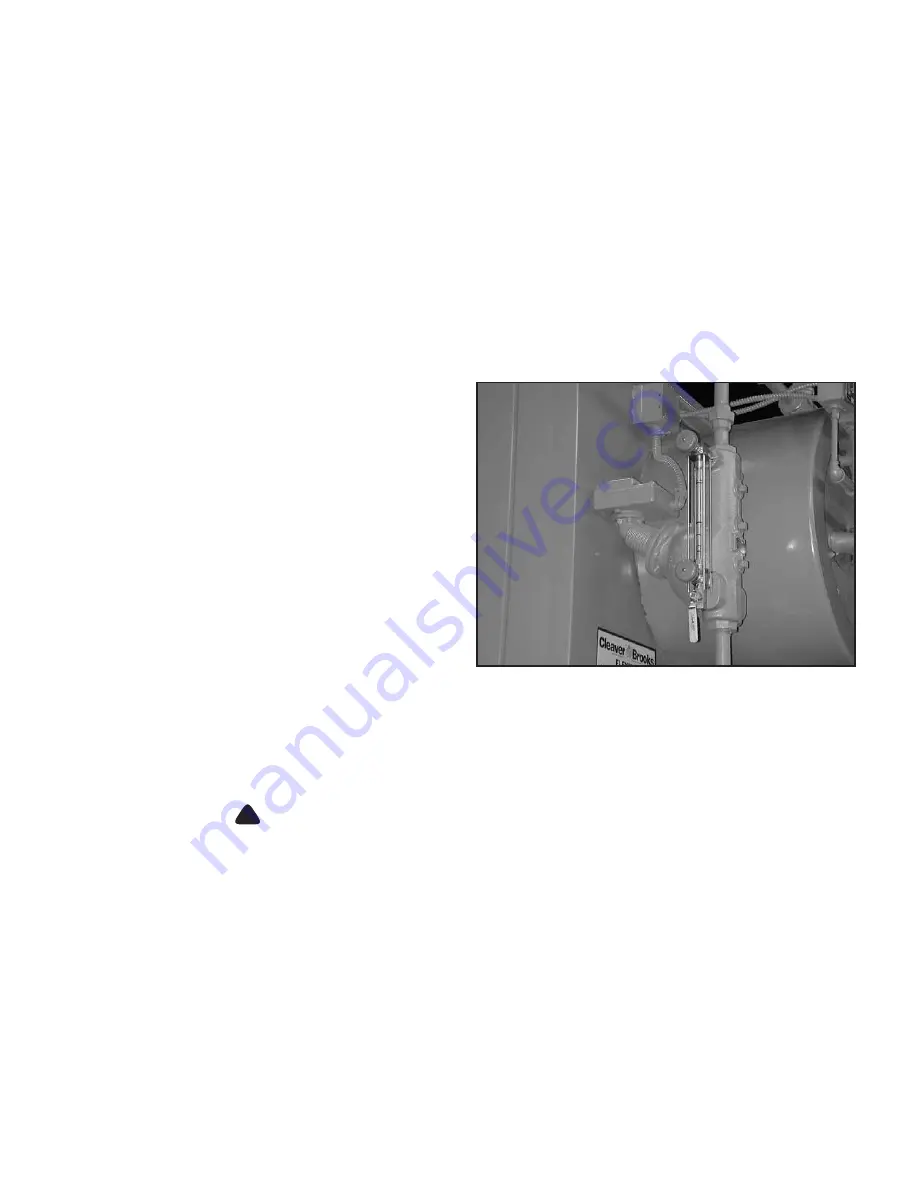
Figure 3-4: Low Water Cutoff and Gauge Glass with
Blowdown Valve
A steam boiler requires periodic blowdown of the
boiler and water column (Figure 3-4). Blowdown is
the removal of some of the concentrated water
from the boiler and the water level control system,
in order to lower the concentration of solids in the
water.
Solids are introduced to the boiler with the
feedwater, even though this water may be treated
prior to use. These solids become less soluble
when the water is heated and evaporated, and tend
to accumulate on heating surfaces.
Periodic blowdown and chemical treatment are
necessary to prevent concentration of solids in the
boiler water, and attachment of these solids to
waterside heating surfaces (scaling).
Scale has a low heat transfer value and acts as an
insulating barrier on heating surfaces. A buildup of
scale will result in lower operating efficiency and,
consequently, higher fuel consumption. More importantly, scale buildup can result in overheating of boiler
metal. This can result in tube failures or other pressure vessel damage.
!
DANGER
CAUTION
Boiler and water level control blowdown must be performed on a regular basis to ensure that con-
centrated solids are removed from the boiler and in order to avoid damage to the equipment.
Water column and gauge glass blowdown valves are located on the water column assembly. The boiler
blowdown tapping(s) can be found at the bottom of the lower drum.
Most blowdown lines are provided with two valves. These are generally a quick-opening valve nearest the
boiler and a slow-opening globe-type valve downstream. Valves will vary depending upon pressure involved
and the make or manufacturer.
Blowdown Procedure
Blowdown is most effective when the boiler water is hot and the burner is being fired at the lowest rate. This
ensures that the water in the boiler is being circulated, and that the solids in the water are in suspension.
Содержание FLX 1000
Страница 12: ...Chapter 1 General Description 1 6 750 177...
Страница 68: ...Chapter 2 Profire V Burner 2 56 750 177...
Страница 90: ...Chapter 4 Sequence of Operation 4 10 750 177...
Страница 104: ...Chapter 5 Adjustment Procedures 5 14 750 177...
Страница 110: ...Chapter 6 Troubleshooting 6 6 750 177...
Страница 122: ...8 2 750 177 Figure 8 1 Typical Hot Water Flextube Casing...
Страница 124: ...8 4 750 177 Figure 8 2 Typical Low Pressure Steam Flextube Casing...
Страница 126: ...8 6 750 177 Figure 8 3 Typical High Pressure Steam Flextube Casing...
Страница 128: ...Parts Chapter 8 8 8 750 177 Steam Pressure Controls...
Страница 129: ...Chapter 8 Parts 750 177 8 9 Water Level Controls...
Страница 130: ...Parts Chapter 8 8 10 750 177 Water Level Controls continued...
Страница 131: ...Chapter 8 Parts 750 177 8 11 Water Column Main and Aux 15 Steam...
Страница 132: ...Parts Chapter 8 8 12 750 177 Water Column Main and Aux 150 Steam...
Страница 133: ...Chapter 8 Parts 750 177 8 13 Safety Valves...
Страница 134: ...Parts Chapter 8 8 14 750 177...
Страница 135: ......
Страница 136: ...e mail info cleaverbrooks com Web Address http www cleaverbrooks com...


