


Chapter 6 — Adjustment Procedures
6-8
Part No. 750-184
To properly set the
Modulating Control
, carefully adjust it under
load conditions, until the load is maintained with the burner firing
at a steady rate. The firing rate at that point may be full high fire or
slightly less, depending upon the relationship of the boiler size to
the load.
When the
Modulating Control
is set and the burner is in full high
fire, the scale setting of the
Modulating Pressure Control
on a steam
boiler will indicate the low point of the modulating range. The scale
setting of the
Modulating Temperature Control
on a hot water boiler
will have a reading that indicates the midpoint of the modulating
range.
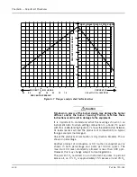
The
Operating Limit
control should now be adjusted and the
differential established. In an installation that does not require a
very close control of steam pressure or water temperature the
adjustable differential (Figure 6-6 A to B) should be set as wide as
conditions permit, since a wide setting will provide less frequent
burner cycling.
The
High Limit Control
provides a safety factor to shut the burner
off in the event the
Operating Limit Control
should fail. The setting
of the control should be sufficiently above the
Operating Limit
Control
to avoid nuisance shutdowns. The setting must be within
the limits of the safety valve settings and should not exceed 90% of
the valve setting. The control requires manual resetting after it shuts
off the burner.
In the setting of the controls, consideration must be given to the
time required for a burner restart. Each start, requires a prepurge
period, plus the fixed time required for proving the pilot and main
flame. In addition, approximately one-half minute is required for the
damper motor to travel from low to high fire. The time lag may allow
pressure or temperature to drop below desirable limits.
F. MODULATING PRESSURE CONTROL (STEAM)
Turn the adjusting screw until the indicator is opposite the low point
of the desired modulating range. Modulated firing will range
between the low point and a higher point equal to the modulating
range of the particular control. In 0-15 psi controls the range is 1/
2 lb; in 5-150 psi controls the range is 5 lbs; in 10-300 psi controls
the range is 12 lbs.
!
Caution
To prevent burner shutdown at other than low-fire setting, adjust the
modulating pressure control to modulate to low fire BEFORE the
operating limit pressure control shuts off the burner. Failure to
follow these instructions could result in damage to the equipment.
G. OPERATING LIMIT PRESSURE CONTROL (STEAM)
Set the “cut-out” (burner-off) pressure on the main scale using the
large adjusting screw. Set the differential on the short scale by
turning the small adjusting screw until the indicator points to the
desired difference between cut-out and cut-in pressures. The “cut-
Содержание CB Ohio Special 100 HP
Страница 2: ...ii ...
Страница 8: ...viii ...
Страница 42: ...Chapter 2 Burner Operation and Control 2 22 Part No 750 184 ...
Страница 116: ...Chapter 6 Adjustment Procedures 6 28 Part No 750 184 ...
Страница 126: ...Chapter 8 Inspection and Maintenance 8 6 Part No 750 184 ...
Страница 153: ...Chapter 9 Parts Part No 750 184 9 3 Insulated Front Head Model CB LE ...
Страница 154: ...Chapter 9 Parts 9 4 Part No 750 184 Insulated Front Head Interior Model CB LE ...
Страница 155: ...Chapter 9 Parts Part No 750 184 9 5 Insulated Inner Door Model CB OS ...
Страница 156: ...Chapter 9 Parts 9 6 Part No 750 184 Insulated Rear Head CB LE ...
Страница 157: ...Chapter 9 Parts Part No 750 184 9 7 Insulated Rear Head CB LE ...
Страница 158: ...Chapter 9 Parts 9 8 Part No 750 184 Insulated Rear Head CB OS ...
Страница 159: ...Chapter 9 Parts Part No 750 184 9 9 Dry Oven Model CB LE ...
Страница 161: ...Chapter 9 Parts Part No 750 184 9 11 Motor Impeller Model CB LE ...
Страница 162: ...Chapter 9 Parts 9 12 Part No 750 184 Front Head Linkage ...
Страница 170: ...Chapter 9 Parts 9 20 Part No 750 184 Control Cabinet Hawk ICS ...
Страница 171: ...Chapter 9 Parts Part No 750 184 9 21 Control Panel Standard ...
Страница 172: ...Chapter 9 Parts 9 22 Part No 750 184 Entrance Box ...
Страница 173: ...Chapter 9 Parts Part No 750 184 9 23 Front Head Electrical CB LE ...
Страница 174: ...Chapter 9 Parts 9 24 Part No 750 184 Front Head Electrical CB LE ...
Страница 175: ...Chapter 9 Parts Part No 750 184 9 25 Front Head Electrical CB OS ...
Страница 176: ...Chapter 9 Parts 9 26 Part No 750 184 Front Head Electrical CB OS ...
Страница 179: ...Chapter 9 Parts Part No 750 184 9 29 Heavy Oil Piping 60 Steam CB LE ...
Страница 180: ...Chapter 9 Parts 9 30 Part No 750 184 Heavy Oil Piping 60 Steam CB LE SEE TABLE NEXT PAGE ...
Страница 181: ...Chapter 9 Parts Part No 750 184 9 31 Common Oil Parts Heavy Oil ...
Страница 182: ...Chapter 9 Parts 9 32 Part No 750 184 Side Mounted Air Compressor Piping ...
Страница 183: ...Chapter 9 Parts Part No 750 184 9 33 Air Compressor Piping CB OS ...
Страница 185: ...Chapter 9 Parts Part No 750 184 9 35 Light Oil Piping ...
Страница 186: ...Chapter 9 Parts 9 36 Part No 750 184 Light Oil Air Piping Front Head ...
Страница 187: ...Chapter 9 Parts Part No 750 184 9 37 Light Oil Air Piping Front Head PAGE 9 31 ...
Страница 191: ...Chapter 9 Parts Part No 750 184 9 41 Gas Train 125 150 HP ...
Страница 193: ...Chapter 9 Parts Part No 750 184 9 43 Gas Train 200 HP ...
Страница 195: ...Chapter 9 Parts Part No 750 184 9 45 Steam Pressure Controls ...
Страница 196: ...Chapter 9 Parts 9 46 Part No 750 184 Hot Water Temperature Controls ...
Страница 197: ...Chapter 9 Parts Part No 750 184 9 47 Water Column ...
Страница 198: ...Chapter 9 Parts 9 48 Part No 750 184 Water Column ...
Страница 199: ...Chapter 9 Parts Part No 750 184 9 49 Fireside Gaskets CB LE ...
Страница 200: ...Chapter 9 Parts 9 50 Part No 750 184 Fireside Gaskets CB OS ...