


Chapter 1 — Basics of Firetube Operation
1-8
Part No. 750-184
7. Water Gauge Glass Drain Valve: Provided to flush the gauge
glass.
8. Vent Valve: Allows the boiler to be vented during filling, and
facilitates routine boiler inspection as required by ASME Code.
9. Stack Temperature Gauge: Indicates flue gas outlet temperature.
10.Auxiliary Low-water Cutoff: Breaks the circuit to stop burner
operation in the event boiler water drops below the master low-
water cutoff point. Manual reset type requires manual resetting
in order to start the burner after a low-water condition.
11.Safety Valve(s): Prevent pressure from exceeding the design
pressure of the vessel. The size, rating and number of valves on
a boiler is determined by the ASME Boiler Code. The safety
valves and the discharge piping are to be installed to conform to
the ASME code requirements. The installation of a valve is of
primary importance to its service life. A valve must be mounted
in a vertical position so that discharge piping and code-required
drains can be properly piped to prevent buildup of back pressure
and accumulation of foreign material around the valve seat area.
Apply only a moderate amount of pipe compound to male threads
and avoid overtightening, which can distort the seats. Use only
flat-jawed wrenches on the flats provided. When installing a
flange-connected valve, use a new gasket and draw the mounting
bolts down evenly. Do not install or remove side outlet valves by
using a pipe or wrench in the outlet.
!
Warning
Only properly certified personnel such as the safety valve
manufacturer’s certified representative can adjust or repair the
boiler safety valves. Failure to follow these instructions could result
in serious personal injury or death.
E. HOT WATER CONTROLS (ALL FUELS)
1. Water Temperature Gauge: Indicates the boiler internal water
temperature.
2. Operating Limit Temperature Control: Breaks a circuit to stop
burner operation on a rise of boiler temperature at a selected
setting. It is adjusted to stop or start the burner at a preselected
operating temperature.
3. High Limit Temperature Control: Breaks a circuit to stop burner
operation on a rise of temperature at a selected setting. It is
adjusted to stop burner at a preselected temperature above the
operating control setting. The high limit temperature control
normally is equipped with a manual reset.
4. Modulating Temperature Control: Senses changing boiler water
temperature and transmits the information to the modulating
motor to change the burner firing rate when the manual-
automatic switch is set on “automatic.”
5. Low-Water Cutoff: Breaks the circuit to stop burner operation if
the water level in the boiler drops below safe operating point,
activating low-water light and optional alarm bell if burner is so
equipped.
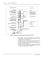
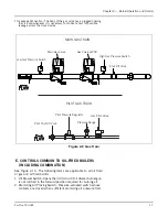
Figure 1-5 Low Water Cutoff (CB-
LE low pressure and CB-OS)
Содержание CB Ohio Special 100 HP
Страница 2: ...ii ...
Страница 8: ...viii ...
Страница 42: ...Chapter 2 Burner Operation and Control 2 22 Part No 750 184 ...
Страница 116: ...Chapter 6 Adjustment Procedures 6 28 Part No 750 184 ...
Страница 126: ...Chapter 8 Inspection and Maintenance 8 6 Part No 750 184 ...
Страница 153: ...Chapter 9 Parts Part No 750 184 9 3 Insulated Front Head Model CB LE ...
Страница 154: ...Chapter 9 Parts 9 4 Part No 750 184 Insulated Front Head Interior Model CB LE ...
Страница 155: ...Chapter 9 Parts Part No 750 184 9 5 Insulated Inner Door Model CB OS ...
Страница 156: ...Chapter 9 Parts 9 6 Part No 750 184 Insulated Rear Head CB LE ...
Страница 157: ...Chapter 9 Parts Part No 750 184 9 7 Insulated Rear Head CB LE ...
Страница 158: ...Chapter 9 Parts 9 8 Part No 750 184 Insulated Rear Head CB OS ...
Страница 159: ...Chapter 9 Parts Part No 750 184 9 9 Dry Oven Model CB LE ...
Страница 161: ...Chapter 9 Parts Part No 750 184 9 11 Motor Impeller Model CB LE ...
Страница 162: ...Chapter 9 Parts 9 12 Part No 750 184 Front Head Linkage ...
Страница 170: ...Chapter 9 Parts 9 20 Part No 750 184 Control Cabinet Hawk ICS ...
Страница 171: ...Chapter 9 Parts Part No 750 184 9 21 Control Panel Standard ...
Страница 172: ...Chapter 9 Parts 9 22 Part No 750 184 Entrance Box ...
Страница 173: ...Chapter 9 Parts Part No 750 184 9 23 Front Head Electrical CB LE ...
Страница 174: ...Chapter 9 Parts 9 24 Part No 750 184 Front Head Electrical CB LE ...
Страница 175: ...Chapter 9 Parts Part No 750 184 9 25 Front Head Electrical CB OS ...
Страница 176: ...Chapter 9 Parts 9 26 Part No 750 184 Front Head Electrical CB OS ...
Страница 179: ...Chapter 9 Parts Part No 750 184 9 29 Heavy Oil Piping 60 Steam CB LE ...
Страница 180: ...Chapter 9 Parts 9 30 Part No 750 184 Heavy Oil Piping 60 Steam CB LE SEE TABLE NEXT PAGE ...
Страница 181: ...Chapter 9 Parts Part No 750 184 9 31 Common Oil Parts Heavy Oil ...
Страница 182: ...Chapter 9 Parts 9 32 Part No 750 184 Side Mounted Air Compressor Piping ...
Страница 183: ...Chapter 9 Parts Part No 750 184 9 33 Air Compressor Piping CB OS ...
Страница 185: ...Chapter 9 Parts Part No 750 184 9 35 Light Oil Piping ...
Страница 186: ...Chapter 9 Parts 9 36 Part No 750 184 Light Oil Air Piping Front Head ...
Страница 187: ...Chapter 9 Parts Part No 750 184 9 37 Light Oil Air Piping Front Head PAGE 9 31 ...
Страница 191: ...Chapter 9 Parts Part No 750 184 9 41 Gas Train 125 150 HP ...
Страница 193: ...Chapter 9 Parts Part No 750 184 9 43 Gas Train 200 HP ...
Страница 195: ...Chapter 9 Parts Part No 750 184 9 45 Steam Pressure Controls ...
Страница 196: ...Chapter 9 Parts 9 46 Part No 750 184 Hot Water Temperature Controls ...
Страница 197: ...Chapter 9 Parts Part No 750 184 9 47 Water Column ...
Страница 198: ...Chapter 9 Parts 9 48 Part No 750 184 Water Column ...
Страница 199: ...Chapter 9 Parts Part No 750 184 9 49 Fireside Gaskets CB LE ...
Страница 200: ...Chapter 9 Parts 9 50 Part No 750 184 Fireside Gaskets CB OS ...


