


Chapter 8 — Inspection and Maintenance
8-28
Part No. 750-184
Notice
Note: The amount and type of grease is very important.
Siemens motors require an aluminum complex high
temperature grease, which may not be mixed with any other
lubricant. Only enough grease should be added to replace
the grease used by the bearing. Either too much or too little
can be harmful. The grease cavity should be filled 1/3 to 1/2
full.
6. With the fill and drain plugs still removed, apply electric power to the
boiler, start the motor, and let it run for approximately 30 minutes.
7. Turn boiler off.
8. Disconnect and lock out electrical power to the boiler.
9. Wipe excess grease from the motor, and install the fill and drain plugs.
Motor is ready for operation.
10.Reconnect electrical power.
W. OIL HEATERS - ELECTRIC, STEAM, HOT WATER
An annual maintenance of the heaters consists primarily of removing the
heating element from the shell and scraping any accumulation of carbonized
oil or sludge deposits that may have collected on the heat exchanging
surfaces.
Before breaking any of the electrical connections to the electric heating
elements, mark all wires and terminals to assure rapid and correct
replacement of wires.
Finish the cleaning process with a cleaning solvent to cut all hardened
deposits from the heater element. Because of the insulating effect of carbon
and sludge, periodic cleaning is necessary to prevent overheating of the
elements. If operation of the heater becomes sluggish, examine the elements
at once and clean as required.
Inspect the shell or tank each time the heater is removed. Flush all
accumulated sludge and sediment from the tank before reinstalling the
heater.
The condensate from steam oil heaters must be safely discharged to waste.
The waste should be checked periodically for any traces of oil that would
indicate leaking tubes within the heater.
The hot water oil heater contains a heat transfer solution. Oil flows through
an inner tube while boiler water surrounds the outer tube. The space
between the two tubes is filled with the heat transfer solution and is
connected to an expansion chamber on the rear of the heater. A visual
indicator on the chamber reveals the presence of any oil if an oil leak occurs.
A 50/50 solution of permanent antifreeze and water is generally used as the
heat transfer solution. If there is no danger of freezing, plain water may be
used as a replenishment if necessary to refill.
Evidence of oil in either the steam heater condensate or in the water heater
indicator demands prompt repairs.
Содержание CB Ohio Special 100 HP
Страница 2: ...ii ...
Страница 8: ...viii ...
Страница 42: ...Chapter 2 Burner Operation and Control 2 22 Part No 750 184 ...
Страница 116: ...Chapter 6 Adjustment Procedures 6 28 Part No 750 184 ...
Страница 126: ...Chapter 8 Inspection and Maintenance 8 6 Part No 750 184 ...
Страница 153: ...Chapter 9 Parts Part No 750 184 9 3 Insulated Front Head Model CB LE ...
Страница 154: ...Chapter 9 Parts 9 4 Part No 750 184 Insulated Front Head Interior Model CB LE ...
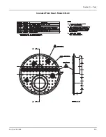
Страница 155: ...Chapter 9 Parts Part No 750 184 9 5 Insulated Inner Door Model CB OS ...
Страница 156: ...Chapter 9 Parts 9 6 Part No 750 184 Insulated Rear Head CB LE ...
Страница 157: ...Chapter 9 Parts Part No 750 184 9 7 Insulated Rear Head CB LE ...
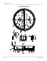
Страница 158: ...Chapter 9 Parts 9 8 Part No 750 184 Insulated Rear Head CB OS ...
Страница 159: ...Chapter 9 Parts Part No 750 184 9 9 Dry Oven Model CB LE ...
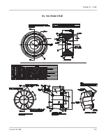
Страница 161: ...Chapter 9 Parts Part No 750 184 9 11 Motor Impeller Model CB LE ...
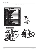
Страница 162: ...Chapter 9 Parts 9 12 Part No 750 184 Front Head Linkage ...
Страница 170: ...Chapter 9 Parts 9 20 Part No 750 184 Control Cabinet Hawk ICS ...
Страница 171: ...Chapter 9 Parts Part No 750 184 9 21 Control Panel Standard ...
Страница 172: ...Chapter 9 Parts 9 22 Part No 750 184 Entrance Box ...
Страница 173: ...Chapter 9 Parts Part No 750 184 9 23 Front Head Electrical CB LE ...
Страница 174: ...Chapter 9 Parts 9 24 Part No 750 184 Front Head Electrical CB LE ...
Страница 175: ...Chapter 9 Parts Part No 750 184 9 25 Front Head Electrical CB OS ...
Страница 176: ...Chapter 9 Parts 9 26 Part No 750 184 Front Head Electrical CB OS ...
Страница 179: ...Chapter 9 Parts Part No 750 184 9 29 Heavy Oil Piping 60 Steam CB LE ...
Страница 180: ...Chapter 9 Parts 9 30 Part No 750 184 Heavy Oil Piping 60 Steam CB LE SEE TABLE NEXT PAGE ...
Страница 181: ...Chapter 9 Parts Part No 750 184 9 31 Common Oil Parts Heavy Oil ...
Страница 182: ...Chapter 9 Parts 9 32 Part No 750 184 Side Mounted Air Compressor Piping ...
Страница 183: ...Chapter 9 Parts Part No 750 184 9 33 Air Compressor Piping CB OS ...
Страница 185: ...Chapter 9 Parts Part No 750 184 9 35 Light Oil Piping ...
Страница 186: ...Chapter 9 Parts 9 36 Part No 750 184 Light Oil Air Piping Front Head ...
Страница 187: ...Chapter 9 Parts Part No 750 184 9 37 Light Oil Air Piping Front Head PAGE 9 31 ...
Страница 191: ...Chapter 9 Parts Part No 750 184 9 41 Gas Train 125 150 HP ...
Страница 193: ...Chapter 9 Parts Part No 750 184 9 43 Gas Train 200 HP ...
Страница 195: ...Chapter 9 Parts Part No 750 184 9 45 Steam Pressure Controls ...
Страница 196: ...Chapter 9 Parts 9 46 Part No 750 184 Hot Water Temperature Controls ...
Страница 197: ...Chapter 9 Parts Part No 750 184 9 47 Water Column ...
Страница 198: ...Chapter 9 Parts 9 48 Part No 750 184 Water Column ...
Страница 199: ...Chapter 9 Parts Part No 750 184 9 49 Fireside Gaskets CB LE ...
Страница 200: ...Chapter 9 Parts 9 50 Part No 750 184 Fireside Gaskets CB OS ...