


Chapter 6 — Adjustment Procedures
Part No. 750-184
6-25
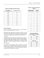
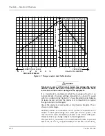
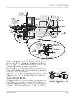
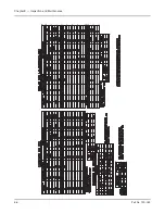
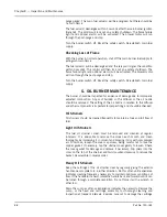
Figure 6-10 Burner Drawer with Gas Pilot
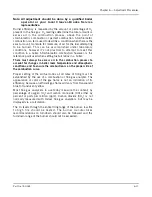
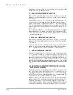
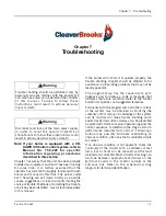
Check the setting of the ignition electrode(s) for proper gap and
position. See Figure 6-10 for the gas pilot electrode and Figure 6-
11 for the light oil pilot. Be sure that the porcelain insulator is not
cracked and that ignition cable connections are tight.
The oil nozzle tip should be seated tightly in the body with the
swirler and the seating spring in place. See Section G in Chapter 8
for additional nozzle tip information.
Check to see that the flame detector sight tube and the gas pilot
tube extend through their respective openings in the diffuser face.
W. OIL DRAWER SWITCH
The integral contacts of the control are closed by proper positioning
and latching of the oil drawer in its forward position (Figure 6-17).
Adjustment of the switch must be such that its contacts open if the
oil drawer is not properly positioned for oil firing. The switch is
BURNER
BACKPLATE
ASSEMBLY
NOZZLE
AIR
PRESSURE
GAUGE
NEOPRENE
“O” RING
OIL
INLET
ATOMIZING
AIR
INLET
IGNITION
ELECTRODE
GAS PILOT
ADJUSTING
COCK
BURNER DRAWER
TUBE
IGNITION
ELECTRODE
ELECTRODE
HOLDER
GAS PILOT PIPE
1
/
4
”
3
/
16
” MAX.
3
/
32
” MIN.
ROTARY
DAMPER
SEAL
RING
STABILIZER
BURNER GUN
OIL NOZZLE BODY
SPIDER
FRONT EDGE OF
DIFFUSER SKIRT
DIFFUSER
OIL NOZZLE
7/16"
GAS
RETAINING
SCREW
ACCESS PLUG
SECONDARY PLUG
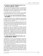
GAS PILOT ASPIRATOR
GAS AND AIR
MIXTURE TO PILOT
IGNITION
ELECTRODE
GLAND
GAS PILOT
ADJUSTING
COCK
AIR
GAS
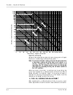
Figure 6-11 Electrode spacing - oil
pilot
1/4”
3/16”
3/16”
Содержание CB Ohio Special 100 HP
Страница 2: ...ii ...
Страница 8: ...viii ...
Страница 42: ...Chapter 2 Burner Operation and Control 2 22 Part No 750 184 ...
Страница 116: ...Chapter 6 Adjustment Procedures 6 28 Part No 750 184 ...
Страница 126: ...Chapter 8 Inspection and Maintenance 8 6 Part No 750 184 ...
Страница 153: ...Chapter 9 Parts Part No 750 184 9 3 Insulated Front Head Model CB LE ...
Страница 154: ...Chapter 9 Parts 9 4 Part No 750 184 Insulated Front Head Interior Model CB LE ...
Страница 155: ...Chapter 9 Parts Part No 750 184 9 5 Insulated Inner Door Model CB OS ...
Страница 156: ...Chapter 9 Parts 9 6 Part No 750 184 Insulated Rear Head CB LE ...
Страница 157: ...Chapter 9 Parts Part No 750 184 9 7 Insulated Rear Head CB LE ...
Страница 158: ...Chapter 9 Parts 9 8 Part No 750 184 Insulated Rear Head CB OS ...
Страница 159: ...Chapter 9 Parts Part No 750 184 9 9 Dry Oven Model CB LE ...
Страница 161: ...Chapter 9 Parts Part No 750 184 9 11 Motor Impeller Model CB LE ...
Страница 162: ...Chapter 9 Parts 9 12 Part No 750 184 Front Head Linkage ...
Страница 170: ...Chapter 9 Parts 9 20 Part No 750 184 Control Cabinet Hawk ICS ...
Страница 171: ...Chapter 9 Parts Part No 750 184 9 21 Control Panel Standard ...
Страница 172: ...Chapter 9 Parts 9 22 Part No 750 184 Entrance Box ...
Страница 173: ...Chapter 9 Parts Part No 750 184 9 23 Front Head Electrical CB LE ...
Страница 174: ...Chapter 9 Parts 9 24 Part No 750 184 Front Head Electrical CB LE ...
Страница 175: ...Chapter 9 Parts Part No 750 184 9 25 Front Head Electrical CB OS ...
Страница 176: ...Chapter 9 Parts 9 26 Part No 750 184 Front Head Electrical CB OS ...
Страница 179: ...Chapter 9 Parts Part No 750 184 9 29 Heavy Oil Piping 60 Steam CB LE ...
Страница 180: ...Chapter 9 Parts 9 30 Part No 750 184 Heavy Oil Piping 60 Steam CB LE SEE TABLE NEXT PAGE ...
Страница 181: ...Chapter 9 Parts Part No 750 184 9 31 Common Oil Parts Heavy Oil ...
Страница 182: ...Chapter 9 Parts 9 32 Part No 750 184 Side Mounted Air Compressor Piping ...
Страница 183: ...Chapter 9 Parts Part No 750 184 9 33 Air Compressor Piping CB OS ...
Страница 185: ...Chapter 9 Parts Part No 750 184 9 35 Light Oil Piping ...
Страница 186: ...Chapter 9 Parts 9 36 Part No 750 184 Light Oil Air Piping Front Head ...
Страница 187: ...Chapter 9 Parts Part No 750 184 9 37 Light Oil Air Piping Front Head PAGE 9 31 ...
Страница 191: ...Chapter 9 Parts Part No 750 184 9 41 Gas Train 125 150 HP ...
Страница 193: ...Chapter 9 Parts Part No 750 184 9 43 Gas Train 200 HP ...
Страница 195: ...Chapter 9 Parts Part No 750 184 9 45 Steam Pressure Controls ...
Страница 196: ...Chapter 9 Parts 9 46 Part No 750 184 Hot Water Temperature Controls ...
Страница 197: ...Chapter 9 Parts Part No 750 184 9 47 Water Column ...
Страница 198: ...Chapter 9 Parts 9 48 Part No 750 184 Water Column ...
Страница 199: ...Chapter 9 Parts Part No 750 184 9 49 Fireside Gaskets CB LE ...
Страница 200: ...Chapter 9 Parts 9 50 Part No 750 184 Fireside Gaskets CB OS ...