background image

45

CE-4 BURNER WIRE DIAGRAM (USED ON CE-330 and CE-440):

13
12
11
10

9
8
7
6
5
4
3
2
1

* VA

LV

E

* L1

* MOTOR

* L2

* IG

NIT

ER

* LIMI

T

*

T

*

 N.

O

.

RE

L

A

Y

WHT

BLACK

ORA

NG

E

RED

GRN

1

1

2

2

3

3

4

4

5

6

5

6


 OI

L

SO

L

E

N

O

ID

PR

O

VI

NG

SW

IT

CH

PR

E

H

E

A

TE

R

T

H

ERM

O

ST

AT

200 WA

TT H

EA

TE

R

SO

L

E

N

O

ID


 AI

R

IG

N

IT

E

R

BU

RNER

 MO

T

O

R

PO

W

E

R

LI

G

H

T

PUM

P

LI

G

H

T

AIR S

WIT

CH

  N.O.

HO

UR

ME

T

E

R

RE

D

RE

D

RE

D

OR

A

N

G

E

VI

O

L

E

T

BL

AC

K

WH

IT

E

CAD

 CELL

BL

UE

BL

A

C

K

AI

R

 C

O

M

P

R

ESSOR


 (

O

P

T

IO

NA

L

)

BL

AC

K

WH

IT

E

BR

O

W

N

WH

IT

E

*

*

T

PRI

M

ARY

 CON

T

R

O

L

WA

L

L T

HE

RM

O

S

TA

T


N.

O.

75

0

4

3

RED

VI

O

L

E

T

WHT

WH

T

W

H

T

BR

O

W

N

CENT

RIF

UG

AL

SWIT

CH

2

0

0

 W

A

TT

 HE

AT

ER

(C

E

-3

3

0 H

OT

 A

IR

 FU

RN

A

CE

)

JU

M

P

ER

 W

IR

E

(C

E

-3

4

0 H

OT

 WA

T

ER BO

ILE

R

)

WIRE DIAGRAMS

Содержание CE-140

Страница 1: ...ace CE 440 Mul Oil Furnace With CE 4 Burner Clean Energy Heating Systems LLC PO Box 1341 540 Maple Street Honey Brook PA 19344 www CleanEnergyHeatingSystems com 888 519 2347 WARNING For your safety DO NOT store gasoline or other flammable vapors and liquids in the vicinity of this or any appliance Heating Systems CE70155 ...

Страница 2: ...egistered trademark of Clean Energy Heating Systems LLC Copyright 2019 Clean Energy Heating Systems LLC This manual may not be reproduced or distributed without the prior written permission of Clean Energy Heating Systems LLC PO Box 1341 540 Maple Street Honey Brook PA 19344 Subject to change without notice ...

Страница 3: ...cting the electrical supply 18 4 Installing the chimney components 19 5 Oil storage tank set up 21 6 Installing the metering pump and oil lines 21 7 Connecting the compressed air line 26 8 Installing the wall thermostat 27 PREPARING THE METERING PUMP FOR START UP 27 STARTING AND ADJUSTING THE BURNER 28 1 Preparing the burner for start up 28 2 Priming the oil pump 28 3 Adjusting the Burner 28 RESET...

Страница 4: ...dicates a hazardous situation which can result in death or serious personal injury if not avoided DANGER Indicates a hazardous situation which will result in death or serious personal injury if not avoided DANGER DO NOT store or use gasoline or other flammable explosive liquids vapors in or around the furnace DANGER DO NOT operate the furnace if excess oil oil vapors or fumes have accumulated in o...

Страница 5: ... the Clean Energy Heating Systems Owner s Manual and in accordance with all regulations and authorities having jurisdiction and the following CSA Standards B139 Oil Burning Equipment B140 General Requirements for Oil Burning Equipment C22 1 Canadian Electrical Code Part 1 GUIDELINES FOR FURNACE USE This furnace is for industrial and or commercial use only This furnace is not intended for residenti...

Страница 6: ...GH PERFORMANCE DO NOT ALLOW ANY UNAPPROVED MATERIAL INTO THE OIL STORAGE TANK Explana on Material placed in the oil storage tank will eventually be delivered to the burner An freeze and water will not ignite and will cause the hea ng equipment to shut down DO NOT USE EXHAUST FANS THAT CREATE A VACUUM IN THE BUILDING Explana on A backdra at the hea ng equipment will damage cri cal burner components...

Страница 7: ...lower housing to the mounting angle brackets on the back of the furnace cabinet 5 Connect the flexible conduit from the blower motor to the rear electrical box 6 Connect the wire leads according to the electrical schematic label in the rear junction box 7 Fasten the blower guards with the remaining 10 self drilling screws to each side of the blower WARNING Blower guards must be in place to prevent...

Страница 8: ...illing screws to secure the blower housing to the mounting angle brackets on the back of the furnace cabinet 4 Fasten the motor bracket and tensioning bracket to the blower according to dimensions shown in Figure 2A 5 Secure the motor to the motor bracket with the supplied hardware CE 250 Blower Assembly Only CAUTION Three shipping brackets are installed on the CE 250 Blower Assembly and must be r...

Страница 9: ... flexible conduit from the blower motor to the rear electrical box and connect the wire leads according to the electrical schematic label in the rear junction box 9 Fasten the blower guards with the remaining 10 self drilling screws to each side of the blower FURNACE ASSEMBLY Figure 2A Blower Assembly Installation CE 330 16 23 6 CE70158 CE 330 CE 440 4 5 18 8 5 Tensioning Bracket CE 330 and CE 440...

Страница 10: ...ower motor Do not operate the blower motor over 85 of the amp rating on the motor nameplate 1 Unit Heater Configuration There are several options for mounting the louvers on a unit heater for free air applications Refer to Figures 3 4 and 5 Cover the unused air outlet openings with the blank covers provided one is painted and one is galvanized The blank covers can be split in two NOTICE When split...

Страница 11: ... 5 Installing the Louvers Splitting the Air Outlet Openings Between one Side and Bottom Figure 4 Installing the Louvers Splitting the Air Outlet Openings Between Both Sides FURNACE ASSEMBLY 11 CE70160 CE70161 ...

Страница 12: ...TICE DO NOT install ductwork over the bottom air outlet opening Proper air flow will not be maintained and furnace damage may occur CE 140 Louvers Mounted on Furnace No Ductwork 1700 CFM 0 30 W C 1400 CFM No Louvers Installed Ductwork Installed on Furnace CE 180 Louvers Mounted on Furnace No Ductwork 1700 CFM 0 30 W C 1400 CFM No Louvers Installed Ductwork Installed on Furnace CE 250 Louvers Mount...

Страница 13: ...re the two over center latches 13 Installing the Burner Figure 6 Proper Position of the Combustion Chamber Target NOTICE The nozzle electrode and retention head may need adjustment after shipping and installation The nozzle should remain centered in the retention head Refer to Figure 7 for proper dimensions 1 Remove the two serrated flange nuts from the front door 2 Slide the blast tube of the bur...

Страница 14: ...ne will need to be disconnected before the door is opened Figure 9 Installing the Connector Block and Oil Line Figure 8 Installing the Burner Power Cord 4 Refer to Figure 8 5 Line up the key in the receptacle with the slot in the cord 6 Tighten the electrical cord when in position NOTICE Make sure the plug and receptacle are properly aligned The ground prong in the receptacle is longer than the ot...

Страница 15: ...ponents 5 Positioning the oil storage tank 6 Installing the metering pump system and oil lines 7 Connecting the compressed air line 8 Installing the wall thermostat 9 Inspecting the furnace installation FURNACE INSTALLATION 8 FT MIN FROM FLOOR TO FURNACE CHECK LOCAL CODES AND NFPA 88 B 8 FT MAXIMUM LIFT DEDICATED ELECTRIC SERVICE OIL PUMP ELECTRICAL CIRCUIT COMPRESSED OIL PRESSURE LINE SUCTION OIL...

Страница 16: ... damage critical burner components Figure 11 Clearances to Combustible Materials Minimum Distances from Combustible Materials WARNING Carefully follow all installation instructions for safe and efficient operation FURNACE INSTALLATION UNIT HEATER UNIT HEATER CENTRAL FURNACE with side warm air outlet with bottom warm air outlet Front burner 60 Front burner 60 Front burner 60 Back blower 2 Back blow...

Страница 17: ...wo nuts on the bottom 4 Use adequately sized square tubing or angle iron across sufficient structural members to safely carry the weight of the furnace 5 Put a washer and two nuts on the top of each all thread rod 6 Use a level to ensure the furnace is hanging level front to back and side to side WARNING Use adequate structural members to safely bear the weight of the furnace when either hanging i...

Страница 18: ...electrician should run wire and make connections to the furnace All wires must be the proper gauge and run in approved electrical conduit All wiring must meet the requirements of the National Electrical Code FURNACE INSTALLATION CE 140 CE 180 120 V 60 Hz Single Phase 20 Amp dedicated circuit 120 V 60 Hz Single Phase 30 Amp dedicated circuit CE 250 CE 330 CE 440 230 V 60 Hz Single Phase 30 Amp dedi...

Страница 19: ...0 and CE 440 furnace models require 8 I D stack components Have a minimum of 10 feet vertical chimney to ensure 02 w c draft over fire Keep horizontal runs short Slope any horizontal sections at least 1 4 per foot Keep the stack installation simple Multiple turns and horizontal runs will reduce the natural draft of the furnace which may damage critical burner components 3 Single wall stack may be ...

Страница 20: ...OPER DRAFT SINGLE WALL STACK COMPONENTS BAROMETRIC DAMPER CLASS A STACK CAP NON RESTRICTIVE TYPE SET DRAFT OVER FIRE AT 0 02 IN W C CE70168 10 FT CE70169 3 FT MIN CLASS A STACK CAP NON RESTRICTIVE TYPE MINIMUM 10 FT VERTICAL STACK HEIGHT TO MAINTAIN PROPER DRAFT BAROMETRIC DAMPER CLASS A STACK COMPONENTS INSTALL AN ADEQUATE WALL SUPPORT SYSTEM TO SAFELY BEAR THE WEIGHT OF THE CLASS A STACK SET DRA...

Страница 21: ...d tank warning label near the fill location Installing the metering pump system and oil lines Metering Pump Installation Guidelines 1 Use non hardening thread sealer for all threaded pipe fittings DO NOT use teflon tape 2 The pump must be installed with the shaft in the horizontal position and the oil outlet pointing up NOTICE The gauge arrow on the front of the pump head must be pointing up CAUTI...

Страница 22: ... water being delivered to the furnace 6 The metering pump system is not weatherproof Mount the pump indoors only Mounting the metering pump assembly NOTICE The metering pump system comes assembled for standard mounting on a wall STANDARD MOUNTING 1 Refer to Figure 17 for a typical metering pump installation standard mounting on a wall 2 Use appropriate hardware to mount the metering pump system to...

Страница 23: ...ing toward the flare 6 Flare the 1 2 copper suction line tubing and install it on the foot valve 7 Insert the suction tubing into the tank and tighten the 2 duplex fitting 8 Carefully bend the 1 2 copper suction line tubing up to the filter and cut it to length 9 Flare the 1 2 copper suction line tubing and install it on the filter Installing the pressure relief oil line back to the tank 1 Refer t...

Страница 24: ... OIL LINE IS ONE CONTINUOUS PIECE OF COPPER TUBING INSTALLED THROUGH THE SLIP FITTING A DETAIL A 1 2 MNPT SLIP THROUGH FITTING 1 2 FLARE FITTING SUCTION OIL LINE 1 2 COPPER TUBING PRESSURE RELIEF RETURN OIL LINE 1 4 COPPER TUBING 2 DUPLEX FITTING 1 2 MNPT X 1 4 COMPRESSION CE70203 PRESSURE RELIEF RETURN OIL LINE TO THE TANK 1 4 COPPER TUBING ...

Страница 25: ... proper performance with variables such as oil temperature and viscosity Clean Energy Heating Systems does not recommend exceeding 150 feet of total pressure oil line 3 It is ideal to have the pressure oil line sloping up from the pump to the furnace This reduces the risk of air pockets and nuisance shut downs 4 Refer to Figure 22 5 Connect the pressure oil line to the aluminum connector block on ...

Страница 26: ...burner Carefully secure the air line to ensure it does not come in contact with any hot metal surfaces NOTICE If a flexible hose is not used the air line will need to be disconnected from the burner to swing the front door open Figure 22 Connecting the Pressure Oil Line to the Connector Block FURNACE INSTALLATION CE70171 AIR LINE CONNECTION 1 4 PUSH TO CONNECT TUBE FITTING ALUMINUM CONNECTOR BLOCK...

Страница 27: ...instructions included with the thermostat to replace the batteries Inspecting the Furnace Installation NOTICE The furnace installation should be inspected by qualified personnel before it is operated to ensure all state and local codes are followed PREPARING THE METERING PUMP FOR START UP Figure 24 Priming the Metering Pump System 1 Refer to Figure 24 2 Remove the 1 2 NPT plug and open the ball va...

Страница 28: ...Release the reset button The yellow light will turn off and the burner will start again 3 Within 15 seconds click push and release the reset button This will transition the primary control to Pump Prime mode which will bypass the flame sensor and keep the pump on for 4 minutes 4 Open the pump bleeder valve and purge all air bubbles from the pump refer to figure 24 5 After 4 minutes the yellow ligh...

Страница 29: ...oil primary control 3 When the combustion chamber has cooled and there is no vapor or excess oil in the combustion chamber push the reset button for 3 seconds and release 4 If the burner does not restart contact the Clean Energy Heating Systems service department WARNING Explosion and Fire Hazard Failure to follow these instructions could result in heavy smoke emission puff back fire and smoke haz...

Страница 30: ...cturers instructions for adjusting the barometric damper to obtain 0 02 w c draft over fire 4 If a proper draft is not obtained follow the instructions below to check for a vacuum in your building Checking for vacuum in your building 1 Have someone slowly open an overhead door while you are taking a draft reading 2 Watch the draft gauge and tell them to stop when you get a 0 02 w c draft over fire...

Страница 31: ... the 4 socket head screws in a crisscross pattern NOTICE Do not over tighten or the aluminum filter casting may crack Cleaning the oil pump head screen 1 Place a container under the oil pump head to catch any released oil 2 Use a 5 32 allen wrench to loosen the pump head cover 3 Remove the cover pump head screen and gasket Carefully scrape the gasket off if any pieces remain stuck to the pump head...

Страница 32: ... irritation 1 Refer to Figure 30 2 Turn OFF power to the furnace and disconnect the power cord from the top of the burner 3 Release the two over center latches on the left side of the front door 4 Carefully open the front clean out door 5 Use a long broom handle or rod to reach to the back and gently remove the combustion chamber target 6 Brush out the combustion chamber and use an industrial vacu...

Страница 33: ...al connector 7 Disconnect the 3 16 copper tubing for the oil gauge 8 Carefully remove the entire aluminum nozzle adapter heater block from the burner 9 Remove all the components from the nozzle adapter heater block 10 Remove all the plugs from the oil ports with a 5 32 allen wrench 11 Clean the nozzle adapter heater block in a parts washer A tube cleaning wire brush rifle barrel cleaning brush can...

Страница 34: ...ter Heater Block MAINTENANCE Nozzle adapter heater block with all components and plugs removed CE70162 CE70175A A A NOZZLE ADAPTER HEATER BLOCK RELEASE RING ON AIR LINE FITTING OIL LINE SWIVEL FITTING QUICK DISCONNECT ELECTRICAL CONNECTOR ...

Страница 35: ...ses as it receives more than 10 psi of air pressure Air Pressure Switch sends power to the Pump Circuit Relay Centrifugal Switch closes and sends power to Air Pressure Switch Pump Circuit Relay closes by receiving power from the valve circuit purple wire on the Oil Primary Control Flame established in combustion chamber Oil Primary Control receives 400 ohm signal from cad cell indicating bright fl...

Страница 36: ...S NOT ON AT PRIMARY CONTROL CHECK TEMPERATURE OF THE NOZZLE ADAPTER HEATER BLOCK HOT COLD ALLOW HEATER BLOCK TO WARM UP FOR APPROX 10 MIN HOT COLD REPLACE HEATER ELEMENT CHECK VOLTAGE ACROSS ALL SWITCHES IN THE LIMIT CIRCUIT PROVING SWITCH MOUNTED ON NOZZLE ADAPTER HEATER BLOCK AUTO HIGH LIMIT SWITCH MOUNTED ON TOP OF FURNACE CABINET HIGH LIMIT SWITCH MOUNTED ON TOP OF FURNACE CABINET REPLACE SWIT...

Страница 37: ... IS NO OIL PRESSURE THERE IS STEADY OIL PRESSURE MAKE SURE IGNITER IS DELIVERING A STRONG SPARK MAKE SURE WATER HAS BEEN DRAINED FROM THE AIR COMPRESSOR MAKE SURE THE OIL BEING DELIVERED TO THE BURNER IS GOOD QUALITY CHECK VOLTAGE ACROSS ALL SWITCHES IN THE PUMP CIRCUIT POST PURGE RELAY AIR PRESSURE SWITCH CENTRIFUGAL SWITCH CHECK FOR REASONS WHY OIL IS NOT BEING DELIVERED TO THE BURNER PLUGGED CA...

Страница 38: ...38 CE70176 767 8 271 2 281 4 271 2 495 8 CE 180 6 Chimney Pipe Diameter Threaded Rod Knock Outs 50 3 8 X 21 3 8 CE 140 6 Chimney Pipe Diameter Threaded Rod Knock Outs 44 5 8 X 21 3 8 CE70177 823 4 55 1 2 271 2 271 2 281 4 ...

Страница 39: ...39 CE 250 6 Chimney Pipe Diameter Threaded Rod Knock Outs 63 5 8 X 21 3 8 1105 8 323 4 287 8 CE70179 735 8 287 8 CE 330 8 Chimney Pipe Diameter Threaded Rod Knock Outs 68 5 8 X 21 3 8 CE70178 991 4 681 2 271 2 281 4 271 2 ...

Страница 40: ...FURNACE DIMENSIONS 40 CE70210 33 1261 2 84 1 2 34 33 CE 440 8 Chimney Pipe Diameter Threaded Rod Knock Outs 79 1 2 X 25 1 2 ...

Страница 41: ...WHITE TO FRONT JUNCTION BOX WHITE CE 180 CE 140 L1 L1 L2 L2 3 4 5 FAN SWITCH HIGH LIMIT AUTO HIGH LIMIT DRAFT INDUCER OPTIONAL OIL PUMP POWER 120 VAC 1 PH L1 L2 GRD TO BLOWER WHITE RED BLACK ORANGE BLACK WHITE CONNECTOR CORD W R WHT RED WHT RED WHT BLK WHT BLK BLACK 75065 BURNER WHITE CE 140 CE 180 USE COPPER CONDUCTORS ONLY DPST POWER SWITCH ...

Страница 42: ... FRONT JUNCTION BOX CE 250 WIRE DIAGRAMS L1 L1 L2 L2 3 4 5 FAN SWITCH HIGH LIMIT AUTO HIGH LIMIT DRAFT INDUCER OPTIONAL OIL PUMP TO BLOWER W R WHT RED WHT RED WHT BLK BLUE 75066 WHITE BLACK CE 250 POWER 120 VAC 1 PH L1 L2 GRD WHITE RED BLACK ORANGE BLACK WHITE CONNECTOR CORD WHT BLK BURNER DPST POWER SWITCH USE COPPER CONDUCTORS ONLY ...

Страница 43: ... BLUE 75067 WHITE BLK CE 330 CE 440 USE COPPER CONDUCTORS ONLY WHT BLK TO BACK GRD WHITE RED BLACK ORG CONNECTOR CORD BURNER DPST POWER SWITCH ELECTRICAL ORANGE BLACK BLUE 75035 WHITE CE 330 CE 440 USE COPPER CONDUCTORS TO FRONT POWER 230 VAC 1 PH 115 V HOT LEG COMMON NEUTRAL GREEN BLACK BOX WHITE MOTOR TO BLOWER 230 Volts ONLY CONTACTOR COIL IS RATED FOR 110 120 VAC REFER TO MOTOR LABEL 115 V HOT...

Страница 44: ...RN 1 1 2 2 3 3 4 4 5 6 5 6 OIL SOLENOID PROVING SWITCH PREHEATER THERMOSTAT 200 WATT HEATER SOLENOID AIR IGNITER BURNER MOTOR POWER LIGHT PUMP LIGHT AIR SWITCH N O HOUR METER RED RED RED ORANGE VIOLET BLACK WHITE CAD CELL BLUE BLACK AIR COMPRESSOR OPTIONAL BLACK WHITE THERMOSTAT BROWN WHITE T PRIMARY CONTROL WALL N O 75005 RED VIOLET WHT WHT WHT BROWN CENTRIFUGAL SWITCH ...

Страница 45: ...PREHEATER THERMOSTAT 200 WATT HEATER SOLENOID AIR IGNITER BURNER MOTOR POWER LIGHT PUMP LIGHT AIR SWITCH N O HOUR METER RED RED RED ORANGE VIOLET BLACK WHITE CAD CELL BLUE BLACK AIR COMPRESSOR OPTIONAL BLACK WHITE BROWN WHITE T PRIMARY CONTROL WALL THERMOSTAT N O 75043 RED VIOLET WHT WHT WHT BROWN CENTRIFUGAL SWITCH 200 WATT HEATER CE 330 HOT AIR FURNACE JUMPER WIRE CE 340 HOT WATER BOILER WIRE DI...

Страница 46: ...46 WIRE DIAGRAMS METERING PUMP GEARMOTOR WIRE DIAGRAM CE70196 PUMP MOTOR SEE FURNACE SCHEMATIC BLUE RED BLACK 7 5 MFD 370 VAC L2 4 ...

Страница 47: ...below along with the wire diagram for your furnace model for additional information about the Burner power Switch Power to the burner must be shut off prior to disconnecting or connecting the Burner Connector Cord Burner Power Switch OFF ON Burner Connector Cord CE70180 ...

Страница 48: ...48 CE 3 CE 4 BURNER ASSEMBLY 1 2 3 4 5 6 7 8 9 11 10 12 15 18 17 13 16 14 19 20 21 22 23 24 25 26 28 30 31 32 27 29 34 33 35 36 37 38 39 40 41 42 43 44 45 46 ...

Страница 49: ...0 24 Z 3 19 20236 Right Side Cover 1 20 30017 Burner Blower Motor 1 21 20034 Motor Mount Plate 1 22 58024 Lock Nut 8 32 Nylon Z 4 23 50015 Squirrel Cage Burner 1 24 30009 Relay SPST 1 25 30016 Hour Meter 1 26 30033 Green Light 1 27 30034 Amber Light 1 28 50019 Primary Control 1 29 50085 Tubing Air Line 1 8 OD 10 30 50061 1 8 Tube 1 8 FP x 90o 1 31 20025 Gauge Mount 1 32 50017 Air Pressure Gauge 1 ...

Страница 50: ...50 NOZZLE ADAPTER HEATER BLOCK ASSEMBLY 2 3 19 5 7 8 15 9 17 14 18 16 13 1 4 6 10 11 12 ...

Страница 51: ...0F Heater 1 7 50364 Tube Fitting 5 32 Tube X 1 8 MNPT 1 8 50024 Swivel Fitting 1 9 30003 Thermostat 120F Proving Switch 1 10 50057 3 16 Compression Nut 1 11 50058 3 16 Compression Ferrule 1 12 50066 3 16 Compression x 1 8 MNPT 1 13 50256 Plunger Air Oil Solenoid 1 14 50253 O Ring Solenoid Inner 1 15 30002 Heat Element 1 16 50022 Solenoid Air Oil 115VAC 1 17 50255 O Ring Solenoid Large 1 18 50254 O...

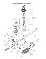
Страница 52: ...52 MANIFOLD BLOCK ASSEMBLY 8 6 2 1 4 17 3 9 5 7 12 13 14 15 16 18 19 11 10 ...

Страница 53: ...50064 1 8 x 1 1 2 Nipple 1 9 50008 Burner Manifold Block 1 10 50364 Tube Fitting 5 32 Tube X 1 8 MNPT 1 11 50365 Tubing Air Line 5 32 OD High Temp 10 12 50022 Solenoid Air Oil 115VAC 1 13 50254 O Ring Solenoid Small 1 14 50255 O Ring Solenoid Large 1 15 50256 Plunger Air Oil Solenoid 1 16 50253 O Ring Solenoid Inner 1 17 30011 Thermostat 150F Heater 1 18 50237 Regulator Manifold Mount Screw In 1 1...

Страница 54: ...54 CE 140 FURNACE CABINET 6 34 33 32 30 29 28 27 26 16 15 14 13 12 11 10 8 9 7 5 4 A 1 2 23 25 24 31 3 17 18 19 20 21 22 A ...

Страница 55: ... 14 50010 Hinge Observation Port 1 15 20080 Observation Port Lid 1 16 20100 Observation Port Ring 1 17 30024 Connector Cord 5 Wire 1 18 20217 Electrical Box Lid 1 19 30072 Burner Power Switch 1 20 20082 Blank Louver Cover Half 2 21 20145 Shroud LH Side CE 140 1 22 30023 Terminal Block 1 23 30008 Thermostat 200F Fan Switch 1 24 30007 Thermostat 290F Aux HL 1 25 30006 Thermostat 200F HL 1 26 20086 T...

Страница 56: ...56 CE 180 FURNACE CABINET 6 18 34 33 32 30 29 28 27 26 22 20 17 16 15 14 13 12 11 10 8 9 7 5 4 A A 1 23 25 24 21 31 3 2 19 ...

Страница 57: ... 14 50010 Hinge Observation Port 1 15 20080 Observation Port Lid 1 16 20100 Observation Port Ring 1 17 30024 Connector Cord 5 Wire 1 18 20217 Electrical Box Lid 1 19 30072 Burner Power Switch 1 20 20082 Blank Louver Cover Half 2 21 20073 Shroud LH Side CE 180 1 22 30023 Terminal Block 1 23 30008 Thermostat 200F Fan Switch 1 24 30007 Thermostat 290F Aux HL 1 25 30006 Thermostat 200F HL 1 26 20086 T...

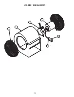
Страница 58: ...58 3 4 6 1 2 5 CE 140 180 BLOWER ...

Страница 59: ...SCRIPTION QTY 60005 CE 140 CE 180 Blower Assembly 1 50013 Blower CE180 1 2 65013 Blower Mtr Bracket 3 4 HP Motor 1 3 30005 Motor 3 4 HP 1 4 30012 Capacitor 15 MFD 370V 1 5 30018 Boot Capacitor 1 6 50018 Blower Guard 2 ...

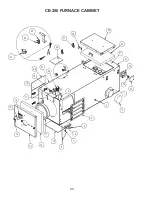
Страница 60: ...60 CE 250 FURNACE CABINET 27 19 29 30 33 34 35 1 2 3 4 5 6 7 8 12 16 15 17 20 21 28 10 9 11 13 14 22 A A 25 24 26 31 32 23 18 ...

Страница 61: ...inge Observation Port 1 15 20080 Observation Port Lid 1 16 20100 Observation Port Ring 1 17 30024 Connector Cord 5 Wire 1 18 20217 Electrical Box Lid 1 19 30072 Burner Power Switch 1 20 20082 Blank Louver Cover Half 2 21 20091 Shroud LH Side CE 250 1 22 30023 Terminal Block 1 23 30008 Thermostat 200F Fan Switch 1 24 30007 Thermostat 290F Aux HL 1 25 30006 Thermostat 200F HL 1 26 20086 Top Switch C...

Страница 62: ...62 2 3 4 5 6 1 CE 250 BLOWER ...

Страница 63: ...M PART DESCRIPTION QTY 60006 CE 250 Blower Assembly 1 50002 Blower CE250 1 2 65014 Blower Mtr Backet 1 HP 1 3 30004 Motor 1HP 1 4 30013 Capacitor 30 MFD 370V 1 5 30018 Boot Capacitor 2 6 50018 Blower Guard 1 ...

Страница 64: ...64 CE 330 FURNACE CABINET 19 3 4 5 6 7 8 10 12 13 14 15 16 20 22 26 27 28 29 30 32 33 35 A A 1 2 9 11 17 21 23 24 25 31 34 18 ...

Страница 65: ...ion Port 1 15 20080 Observation Port Lid 1 16 20100 Observation Port Ring 1 17 30024 Connector Cord 5 Wire 1 18 20217 Electrical Box Lid 1 19 30072 Burner Power Switch 1 20 20130 Blank Louver Cover half CE 330 2 21 20123 Shroud LH Side CE 330 1 22 30023 Terminal Block 1 23 30008 Thermostat 200F Fan Switch 1 24 30007 Thermostat 290F Aux HL 1 25 30006 Thermostat 200F HL 1 26 20086 Top Switch Cover 1...

Страница 66: ...66 CE 330 BLOWER 12 8 7 4 13 1 2 3 5 6 9 10 11 ...

Страница 67: ...330 Blower Wheel Bushing 1 1 5 50131 CE330 Blower Drive Belt 1 6 65023 Belt Guard CE 330 WA 1 7 50170 CE330 Blower Motor Bushing 5 8 1 8 50246 Key CE 330 Blower Motor Shaft 1 9 50128 CE330 Blower Motor Pulley 1 10 20133 Tensioning Bracket 1 11 30060 CE330 Blower Motor 2 HP 1 12 20132 Blower Motor Mount CE330 1 13 50123 Blower Guard 1 ...

Страница 68: ...68 CE 440 FURNACE CABINET 19 3 4 5 6 7 8 10 12 13 14 15 16 20 22 26 27 28 29 30 32 33 35 A A 1 2 9 11 17 21 23 24 25 31 34 18 ...

Страница 69: ...Hinge Observation Port 1 15 20080 Observation Port Lid 1 16 20100 Observation Port Ring 1 17 30024 Connector Cord 5 Wire 1 18 20217 Electrical Box Lid 1 19 30072 Burner Power Switch 1 20 20287 Blank Louver Cover half CE 440 2 21 20291 Shroud LH Side CE 440 1 22 30023 Terminal Block 1 23 30008 Thermostat 200F Fan Switch 1 24 30007 Thermostat 290F Aux HL 1 25 30006 Thermostat 200F HL 1 26 20086 Top ...

Страница 70: ...70 CE 440 BLOWER 12 8 7 4 13 1 2 3 5 6 9 10 11 ...

Страница 71: ...330 CE 440 Blower Wheel Bushing 1 1 5 50377 CE440 Blower Drive Belt 1 6 65040 Belt Guard CE 440 WA 1 7 50170 CE330 CE 440 Blower Motor Bushing 5 8 1 8 50246 Key CE 330 CE 440 Blower Motor Shaft 1 9 50376 CE440 Blower Motor Pulley 1 10 20133 Tensioning Bracket 2 11 30060 Blower Motor 2 HP 1 12 20296 Blower Motor Mount CE440 1 13 50123 Blower Guard 1 ...

Страница 72: ...72 METERING PUMP ASSEMBLY WITH A2RA 7720 PUMP HEAD 3 1 2 4 6 7 8 9 10 11 12 13 14 15 16 17 18 19 20 22 23 5 21 ...

Страница 73: ...1 Bushing 3 4 x 1 2 NPT 1 10 50036 1 2 MNPT x 1 4 Comp 1 11 USER SUPPLIED 1 2 Copper Tubing 12 50070 Foot Valve 1 2 1 13 50034 1 2 Flare Nut 45 o 2 14 50044 Duplex Fitting 2 1 15 50035 Slip Through Fitting 1 2 MNPT 1 16 50033 1 2 Flare x 1 2 NPT Brass 2 17 50053 Ball Valve 1 2 NPT 2 18 50037 Tee 1 2 F x 1 2 F x 1 2 M 1 19 50038 Plug 1 2 NPT Hex 1 20 50030 Bushing 3 4 x 1 4 NPT 1 21 40014 Metering ...

Страница 74: ...RESTOR CAP 8 90155 DEKTITE BOOT 7 KIT 90158 DEKTITE BOOT 9 KIT 90174 SINGLE WALL 6 X24 SS 90168 SINGLE WALL 8 X24 SS 90172 SW TEE 8 SS 90178 SW TEE 6 SS 90008 WALL FIRESTOP 6 90010 STORM COLLAR 6 90011 FLASHING 2 12 5 12 6 90097 WALL FIRESTOP 8 90102 STORM COLLAR 8 90105 FLASHING 2 12 5 12 8 90065 INSULATED STACK 8X36 SS 90069 INSULATED STACK 8X18 SS 90071 INSULATED STACK 8X12 SS 90018 INSULATED S...

Страница 75: ...ADAPTOR 6 90178 SW TEE 6 SS 90172 SW TEE 8 SS 90168 SINGLE WALL 8 X24 SS 90174 SINGLE WALL 6 X24 SS 90177 SINGLE WALL ELBOW 6 SS 90171 SINGLE WALL ELBOW 8 SS 90093 ADJUSTABLE ROOF SUPPORT 8 90006 ADJUSTABLE ROOF SUPPORT 6 90008 WALL FIRESTOP 6 90097 WALL FIRESTOP 8 90082 CEILING SUPPORT 8 USED WITH INSULATED CEILING 90098 INSULATION SHIELD 8 90102 STORM COLLAR 8 90105 FLASHING 2 12 5 12 8 90018 IN...

Страница 76: ...R PUMP HEAD THE HEAT STORAGE NOZZLE ADAPTER HOURS FILTER SCREEN EXCHANGER TANK HEATER BLOCK CLEAN THE OIL CANISTER FILTER ONCE PER YEAR CLEAN THE PUMP HEAD SCREEN ONCE PER YEAR CLEAN ASH FROM THE HEAT EXCHANGER 1200 HOURS CLEAN THE NOZZLE ADAPTER HEATER BLOCK 2000 TO 3000 HOURS ...

Страница 77: ...must complete and return the Warranty Registration Card within thirty 30 days of purchase to activate TWO YEAR Parts Warranty Coverage B The equipment must be fired at rated capacity only with fuels listed on data label C The equipment must be installed operated and maintained in accordance with Federal State and Local regulations as well as with all MANUFACTURER S installation and operating instr...

Страница 78: ...LACE STAMP HERE CLEAN ENERGY HEATING SYSTEMS LLC PO Box 1341 HONEY BROOK PA USA 19344 Approved Method to Dispose of Waste Oil Clean Energy Heating Systems LLC PO Box 1341 540 Maple Street Honey Brook PA 19344 www CleanEnergyHeatingSystems com 888 519 2347 ...

Отзывы: