26
Connecting the Compressed Air Line:
Figure 23: Installing the Air Line
(1) Refer to Figure 23.
(2) mount a water trap / air regulator (adjusted
to 50 psi) and shut-off valve close to the
furnace.
(3) Run a flexible hose to the air inlet on the
side of the burner. Carefully secure the air
line to ensure it does not come in contact
with any hot metal surfaces.
NOTICE:
If a flexible hose is not used the
air line will need to be disconnected from the
burner to swing the front door open.
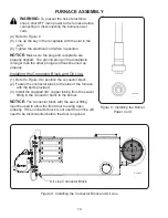
Figure 22: Connecting the Pressure Oil Line to the Connector Block
FURNACE INSTALLATION
CE70171
AIR LINE CONNECTION
(1/4" PUSH-TO-CONNECT
TUBE FITTING)
ALUMINUM CONNECTOR BLOCK
OIL INLET PORT (1/4" NPT)
CE70170
SWIVEL FITTING
Содержание CE-140
Страница 50: ...50 NOZZLE ADAPTER HEATER BLOCK ASSEMBLY 2 3 19 5 7 8 15 9 17 14 18 16 13 1 4 6 10 11 12 ...
Страница 52: ...52 MANIFOLD BLOCK ASSEMBLY 8 6 2 1 4 17 3 9 5 7 12 13 14 15 16 18 19 11 10 ...
Страница 58: ...58 3 4 6 1 2 5 CE 140 180 BLOWER ...
Страница 62: ...62 2 3 4 5 6 1 CE 250 BLOWER ...
Страница 66: ...66 CE 330 BLOWER 12 8 7 4 13 1 2 3 5 6 9 10 11 ...
Страница 70: ...70 CE 440 BLOWER 12 8 7 4 13 1 2 3 5 6 9 10 11 ...
Страница 72: ...72 METERING PUMP ASSEMBLY WITH A2RA 7720 PUMP HEAD 3 1 2 4 6 7 8 9 10 11 12 13 14 15 16 17 18 19 20 22 23 5 21 ...


