11/15/2018
4-1
Sect04_CSM_a.fm
Section IV
OPERATING
INSTRUCTIONS
4.1
G
ENERAL
The instructions in this section describe the
standard startup and shutdown procedures for your
Clayton Steam Master steam generator.
Your Clayton Steam Master offer two
operating modes, auto mode and manual mode.
These two operating modes are covered in the
following sections.
The manual operating mode is reserved
for more advanced, knowledgeable
users who are thoroughly familiar with
the Clayton Steam Master steam
generator.
4.2
M
AIN
M
ENU
S
CREEN
The main menu provides basic Clayton
contact information, machine information, and
access points to selected operation screens. This
screen is accessed by pressing the MAIN MENU
icon at the bottom-right corner of the various
operating screens.
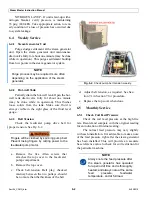
Not all icons will appear on the main menu
screen, as shown in Fig. 4-1. The icons will be
either active or inactive depending on the operator
access level. The advanced-level screens require
user login. Once logged in, the icons for the
advanced-level screens will become active.
4.3
S
TART
UP
A
UTO
M
ODE
The default start is auto mode. The unit
may be transferred into manual mode
by the AUTO/MANUAL button on the
main menu once the unit is started.
Manual mode operation requires the operator
to be present and actively monitoring the unit
throughout this period.
The start-up screen in Fig. 4-2 displays after
power-on. Verify and set, as needed, the valve
positions as indicated on the screen. Acknowledge
each valve on the screen following verification that
the indicated valve is in the correct position; i.e.:
the valve is either open or closed.
Once the final valve position has been
acknowledged, the unit will start to auto fill. The
unit will fill at a preprogrammed fill rate of 20%.
Fig. 4-1.
Main Menu screen.
Содержание Steam Master CSMG-15
Страница 1: ...STEAM MASTER SERIES USER MANUAL Cover CSMG 15 30 40 R027880B 20190603 ...
Страница 8: ...vi The controls and features may differ depending on the unit s size and specifications ...
Страница 9: ...vii The controls and features may differ depending on the unit s size and specifications ...
Страница 14: ...Specifications_CSM_a fm xii 11 22 2018 This page intentionally left blank ...
Страница 26: ...Sect02_CSMG_b fm 2 6 04 19 2019 Steam Master Instruction Manual This page intentionally left blank ...
Страница 44: ...Sect05_CSMG_a fm 5 6 11 26 2018 Steam Master Instruction Manual NOTES ...
Страница 56: ...Sect06_CSMG_b fm 6 12 04 22 2019 Steam Master Instruction Manual This page intentionally left blank ...
Страница 66: ...Sect07_CSMG_b fm 7 10 04 26 2019 Steam Master Instruction Manual This page intentionally left blank ...
Страница 68: ...HeatingSect_SM15_a fm A 2 04 30 2019 Fig 01A Main Heating Section SM15 ...
Страница 69: ...04 30 2019 A 3 HeatingSect_SM15_a fm FIG 01A Main Heating Section SM15 ...
Страница 70: ...HeatingSect_SM15_a fm A 4 04 30 2019 Fig 01B Economizer Stack Outlet Kit SM15 ...
Страница 71: ...04 30 2019 A 5 HeatingSect_SM15_a fm FIG 01B Economizer Stack Outlet Kit SM15 ...
Страница 72: ...HeatingSect_SM30_b fm A 6 12 05 2018 Fig 01C Main Heating Section SM30 ...
Страница 73: ...12 05 2018 A 7 HeatingSect_SM30_b fm FIG 01C Main Heating Section SM30 ...
Страница 74: ...HeatingSect_SM30_b fm A 8 12 05 2018 Fig 01D Economizer Coil SM30 ...
Страница 75: ...12 05 2018 A 9 HeatingSect_SM30_b fm FIG 01D Economizer Coil SM30 ...
Страница 76: ...HeatingSect_SM45_b fm A 10 04 30 2019 Fig 01C Main Heating Section SM40 ...
Страница 77: ...04 30 2019 A 11 HeatingSect_SM45_b fm FIG 01C Main Heating Section SM40 ...
Страница 78: ...HeatingSect_SM45_b fm A 12 04 30 2019 Fig 01D Economizer Coil SM40 Sht 1 of 2 ...
Страница 79: ...04 30 2019 A 13 HeatingSect_SM45_b fm FIG 01D Economizer Coil SM40 ...
Страница 80: ...Sep Trap PressMfld_SM153040_b fm A 14 04 30 2019 Fig 02A Steam Discharge and Separator Hookup SM 15 ...
Страница 81: ...04 30 2019 A 15 Sep Trap PressMfld_SM153040_b fm FIG 02A Steam Discharge and Separator Hookup SM 15 ...
Страница 82: ...Sep Trap PressMfld_SM153040_b fm A 16 04 30 2019 Fig 02B Steam Discharge and Separator Hookup SM 30 40 ...
Страница 83: ...04 30 2019 A 17 Sep Trap PressMfld_SM153040_b fm FIG 02B Steam Discharge and Separator Hookup SM 30 40 ...
Страница 86: ...Sep Trap PressMfld_SM153040_b fm A 20 04 30 2019 Fig 02E Pressure Indicating System ...
Страница 87: ...04 30 2019 A 21 Sep Trap PressMfld_SM153040_b fm FIG 02E Pressure Indicating System ...
Страница 90: ...PumpHkup C1 C2_parts_a fm A 24 03 05 2019 Fig 05A Pump Assy C1 ...
Страница 91: ...03 05 2019 A 25 PumpHkup C1 C2_parts_a fm FIG 05A Pump Assy C1 ...
Страница 92: ...03 05 2019 A 26 PumpHkup C1 C2_parts_a fm Fig 05B Pump Assy C2 ...
Страница 93: ...PumpHkup C1 C2_parts_a fm A 27 03 05 2019 FIG 05B Pump Assy C2 ...
Страница 98: ...Blank_Left fm A 32 08 16 2017 This page intentionally left blank ...
Страница 104: ...25 75 bhp Feedwater Skid Option FeedwtrSkid_VHtwl_25 75bhp_a fm B 6 11 26 2018 This page intentionally left blank ...
Страница 106: ...R027906A 2018 10 22 ...
Страница 107: ...NOTES ...
Страница 108: ...Steam Generator Instruction Manual This page intentionally left blank ...
Страница 109: ......

