background image

2

OPERATIONAL SAFETY

1.

Carefully read and follow all caution decals. 
(See Pg. 5.)

2.

Operate only in daylight or good artificial light.

3.

Do not operate machine unless all guards, shields and
covers are in place and in proper working condition.

4.

It is essential all operator safety mechanisms be
connected and in operating condition prior to use.

5.

Do not change the engine governor settings or over-
speed the engine. Operating an engine at excessive
speed may increase the hazard of personal injury.

6.

Disengage the drive control(s) and tine lowering
handle before starting. (See Pg. 3, Fig 1.)

7.

Start the engine carefully with feet well away from
the tines.

8.

Do not put hands, feet or clothing near rotating parts
while the unit is being operated.

9.

Travel up and down slopes at a 45 degree angle rather
than across, to prevent unit from tipping over.

10. Exercise extreme caution when changing direction on

slopes. Do not get too close to sharp drop-offs or
operate unit on excessively steep slopes. 

DO NOT

release control handle(s) on a slope, this will cause
free wheeling, allowing unit to roll back down the
slope. Make sure to leave yourself room to correct the
problem if one arises.

11. Use caution when pulling the unit towards you.

12. Always stop the tines if unit has to be tilted for

transportation or when crossing surfaces (i.e.
sidewalks, driveways, stepping stones, etc.).

13. Never pick up or carry an Aerator while the engine 

is running.

14. Stop the engine and disconnect the spark plug wire:

a) before checking, cleaning or working on unit, and
b) after striking a foreign object (inspect the unit for
damage and make repairs before restarting and
operating).

15. Stop the engine: a) whenever you leave the unit,

b) before refueling, and c) before clearing blockages.

16. Reduce the throttle setting during engine run-out and,

if the engine is provided with shut-off valve, turn the
fuel off at the conclusion of operating.

SAFETY PRECAUTIONS

TRAINING

1.

Regard the unit as a piece of power equipment and
teach this regard to all who operate this unit.

2.

Read the instructions carefully. Be familiar with the
controls and the proper use of the equipment.

3.

Never allow children, teenagers or people unfamiliar
with these instructions to use this piece of equipment.

4.

Avoid operating unit while people, especially children
or pets, are nearby. Keep in mind that the operator or
user is responsible for accidents or hazards occurring
to other people or their property.

5.

Be sure you know how to stop the Aerator at a
moments notice.

PREPARATION SAFETY

1.

The use of personal protective equipment, such as (but
not limited to) protection for the eyes, ears, feet and
head is recommended.

2.

While operating, always wear substantial foot wear
and long trousers. Do not operate the equipment when
barefoot or wearing open sandals.

3.

Area should be free of all obstacles and debris.

ENGINE SAFETY

1.

Handle gasoline with care; it is highly flammable.

2.

Use an approved gasoline container.

3.

Always add fuel before starting the engine.

4.

Fill the fuel tank outdoors.

5.

If fuel is spilled, do not attempt to start the engine.
Move away from the area of the spill and avoid
creating any source of ignition until fuel vapors have
dissipated.

WARNING

DO NOT FILL TANK COMPLETELY FULL.

DO NOT SMOKE WHILE YOU FILL FUEL TANK.

DO NOT REMOVE GAS CAP IF ENGINE 

IS RUNNING.

DO NOT OPERATE ENGINE IN A 

CONFINED SPACE WHERE DANGEROUS 

CARBON MONOXIDE FUMES CAN COLLECT.

Содержание 48-RT

Страница 1: ...ERATOR S MANUAL AERATOR MODELS CA 18 Compact Aerator TA 17D TA 25D Split Drive Aerators TA 19D TA 26D Turf Aerators 48 RT 60 RT 72 RT Tow Aerators 1028 Street Road P O Box 38 Southampton PA 18966 U S...

Страница 2: ...RATOR 6 Parts Main Frame 6 Parts Power Train and Tine Rotor Assembly 7 Parts Handle and Control 8 TA 17D SPLIT DRIVE AERATOR 9 Parts Main Frame 9 Parts Power Train Assembly 10 Parts Handle and Control...

Страница 3: ...tor READ THIS MANUAL Read this manual carefully in its entirety It contains safety operating maintenance and adjustment instructions for your Aerator By following the operating and maintenance instruc...

Страница 4: ...make repairs before restarting and operating 15 Stop the engine a whenever you leave the unit b before refueling and c before clearing blockages 16 Reduce the throttle setting during engine run out an...

Страница 5: ...orting from one work area to another by lifting up on lowering handle see Fig 1 2 Aerator can be transported with the engine running or with the engine off WARNING CAUTION TO AVOID INJURY DO NOT PLACE...

Страница 6: ...er clutch arm pivot bearing See Fig 2 Check roller chain s for tightness Follow these steps Model CA 18 See Fig 3 1 Disconnect spark plug 2 Take off pulley guard by removing two nuts and lock washers...

Страница 7: ...HT STORAGE INSTRUCTIONS Before the Aerator is put into storage for any period exceeding 30 days the following steps should be taken 1 Drain all fuel from fuel tank and fuel lines 2 Start engine and ru...

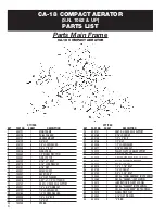
Страница 8: ...100250 2 SPRING Parts Main Frame CA 18 COMPACT AERATOR S N 1062 UP PARTS LIST QTY PER KEY PART NO SHEET DESCRIPTION 24 400141 1 ARM R H REAR AXLE SUPPORT 25 500169 2 5 16 LOCK NUT 26 500149 2 1 2 x 2...

Страница 9: ...SPROCKET 40 B27 x 1 22 500003 1 1 4 x 7 8 HALF MOON KEY 23 300073 1 SPACER TINE SHAFT 24 100248 2 BEARING PLATEDFLANGEw COLLAR 1 2BOLT 25 100254 1 CHAIN 40 x 109 PITCH 26 100025 1 CONNECTING LINK 27...

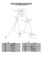
Страница 10: ...3 8 NUT 8 500041 27 3 8 LOCK NUT 9 500178 2 3 8 x 3 1 4 BOLT 10 100251 2 HANDLE LOCK RING CA 18 COMPACT AERATOR QTY PER KEY PART NO SHEET DESCRIPTION 11 400130 1 ARM L H LINKAGE 12 500091 4 3 8 x 2 B...

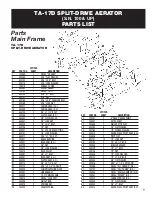
Страница 11: ...LT 32 500114 4 5 16 x 2 1 4 TAP BOLT 33 300049 4 CHAIN TIGHTENING PLATE 34 300007 2 LINKAGE ARM 35 400080 1 TA 17D MAIN FRAME 36 100074 3 DECAL CLASSEN 37 400056 1 WEIGHT BAR 38 400015 2 SPRING ARM 39...

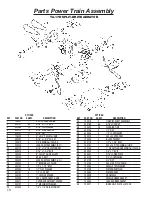
Страница 12: ...132 2 1 OUTSIDE SPACER 20 200009 2 40 x 36 SPROCKET HUB 21 300011 2 OUTSIDE DRUM SHAFT SPACER 22 300131 2 2 MACHINERY WASHER 23 500003 2 1 4 x 7 8 HALF MOON KEY QTY PER KEY PART NO SHEET DESCRIPTION 2...

Страница 13: ...091 1 CONTROL HANDLE R H 7 500041 9 3 8 LOCK NUT 8 500130 6 3 8 LOCK WASHER 9 500129 6 3 8 NUT 10 100034 2 CLUTCH CABLE SPRING QTY PER KEY PART NO SHEET DESCRIPTION 11 400018 1 MAIN HANDLE 12 500043 6...

Страница 14: ...4 4 5 16 x 2 1 4 TAP BOLT 33 300049 4 CHAIN TIGHTENING PLATE 34 300007 2 LINKAGE ARM 35 400079 1 TA 25D MAIN FRAME 36 100074 3 DECAL CLASSEN 37 400057 1 WEIGHT BAR 38 400015 2 SPRING ARM 39 100040 2 F...

Страница 15: ...500131 8 1 2 LOCK NUT 19 300011 2 OUTSIDE DRUM SHAFT SPACER 20 200009 2 40 x 36 SPROCKET HUB 21 300131 2 2 MACHINERY WASHER 22 500003 2 1 4 x 7 8 HALF MOON KEY QTY PER KEY PART NO SHEET DESCRIPTION 23...

Страница 16: ...090 1 CONTROL HANDLE R H 7 500041 9 3 8 LOCK NUT 8 500130 6 3 8 LOCK WASHER 9 500129 6 3 8 NUT 10 100034 2 CLUTCH CABLE SPRING QTY PER KEY PART NO SHEET DESCRIPTION 11 400028 1 MAIN HANDLE 12 500043 6...

Страница 17: ...HER 2 NUTS 29 300037 1 PLATE ADJUSTER 30 500005 4 5 16 X 1 1 2 BOLT W LOCK WASHER NUT NOT SHOWN 31 300009 1 WEIGHT STOP 32 _ 300071 1 PLATE HANDLE BRACE GUSSET 33 500051 6 3 8 X 1 BOLT W LOCK NUT 34 1...

Страница 18: ...2 FLAT WASHERS LOCK NUT 24 500042 1 WASHER 3 8 FLAT 25 500051 6 3 8 X 1 BOLT W LOCK NUT 26 100032 30 TINE PLUGGING 27 400071 1 GUARD CHAIN 28 300007 2 ARM LINKAGE 29 400017 1 HANDLE LOWERING 30 500049...

Страница 19: ...ONDA QTY PER KEY PART NO SHEET DESCRIPTION 1 700009 1 AXLE DRUM 2 100004 4 BEARING w ECCENTRIC COLLAR 1 PILLOW BLOCK 3 500040 8 1 2 x 1 3 4 BOLT w FLAT WASHER LOCK NUT 4 100083 1 WASHER SMALL STEEL 5...

Страница 20: ...1 CONNECTING LINK 40 7 100032 30 TINE PLUGGING 8 500128 60 5 16 x 1 1 2 BOLT w LOCK NUT 9 500040 8 1 2 x 1 3 4 BOLT w FLAT LOCK NUT 10 200009 1 SPROCKET w 1 HUB 40 x 36 11 100004 4 BEARING w ECCENTRI...

Страница 21: ...2 BOLTW 2 FLATWASHERS LOCKWASHER 2 NUTS 29 300037 1 PLATE ADJUSTER 30 500005 4 5 16 X 1 1 2 BOLT W LOCK WASHER NUT NOT SHOWN 31 300009 1 WEIGHT STOP 32 300071 1 PLATE HANDLE BRACE GUSSET 33 500051 6...

Страница 22: ...H 23 500107 1 3 8 X 1 BOLT W 2 FLAT WASHERS LOCK NUT 24 500042 1 WASHER 3 8 FLAT 25 500051 6 3 8 X 1 BOLT W LOCK NUT 26 100032 42 TINE PLUGGING 27 400071 1 GUARD CHAIN 28 300007 2 ARM LINKAGE 29 40002...

Страница 23: ...ONDA QTY PER KEY PART NO SHEET DESCRIPTION 1 700010 1 AXLE DRUM 2 100004 4 BEARING w ECCENTRIC COLLAR 1 PILLOW BLOCK 3 500040 8 1 2 x 1 3 4 BOLT w FLAT WASHER LOCK NUT 4 100083 1 WASHER SMALL STEEL 5...

Страница 24: ...1 CONNECTING LINK 40 7 100032 42 TINE PLUGGING 8 500128 84 5 16 x 1 1 2 BOLT w LOCK NUT 9 500040 8 1 2 x 1 3 4 BOLT w FLAT LOCK NUT 10 200009 1 SPROCKET w 1 HUB 40 x 36 11 100004 4 BEARING w ECCENTRI...

Страница 25: ...00159 8 3 8 x 3 BOLT 18 100032 48 TINE Parts Main Frame 48 RT TOW AERATOR S N 000337 UP PARTS LIST QTY PER KEY PART NO SHEET DESCRIPTION 19 700026 2 TINE SHAFT 20 300106 2 TINE END SPACER 21 300058 2...

Страница 26: ...59 8 3 8 x 3 BOLT 18 100032 60 TINE Parts Main Frame 60 RT TOW AERATOR S N 000161 UP PARTS LIST QTY PER KEY PART NO SHEET DESCRIPTION 19 700027 2 TINE SHAFT 20 300106 2 TINE END SPACER 21 300058 2 CEN...

Страница 27: ...159 8 3 8 x 3 BOLT 18 100032 72 TINE Parts Main Frame 72 RT TOW AERATOR S N 144 UP PARTS LIST QTY PER KEY PART NO SHEET DESCRIPTION 19 700029 2 TINE SHAFT 20 300106 2 TINE END SPACER 21 300058 2 CENTE...

Страница 28: ...chantability and fitness for a particular purpose are limited to two years from the date of purchase and to the extent permitted by law any and all implied warranties are excluded The above remedy of...

Страница 29: ......
Страница 30: ...ility for variations which may be evident in the actual specifications of its products and the statements and descriptions contained in this publication COMPACT AERATORS CA 18H CA 18B SPLIT DRIVE AERA...

Отзывы: